Gunslinger. Because getting up is just too hard.

Leave a comment

What is it?

Some people have a really hard time waking up and getting out of bed everyday (including us). To ensure that they won’t be late for work or class people have found their solutions to themselves out of bed. Some use more than one alarm clock and others even place their alarm clock into the bathroom, so they can immediately take their ice-cold wake-up-shower. But what if the alarm clock is too quiet and overheard? Catastrophe. Worry no more, dear friend: the Gunslinger Alarm Clock is here. This baby will get you out of bed faster than you can say “What-the-hell-is-happening-and-how-do-I-make-this-thing-stop?”.

First, you choose when you’d like to wake up just as with any other alarm clock. Once the alarm starts at the chosen time, the Gunslinger Alarm Clock then uses its gun to shoot a rather tiny ball through the bedroom that is needed to turn off the tremendously loud alarm. That means you have to get up and go look for it, and trust us – you will! If you want to speed up the searching process, the gun can be aimed at a particular point in your room, otherwise the position can be randomized.

How does it work?

The gun can perform two basic movements to aim: it can turn 180 degrees left-to-right and 120 degrees up and down. For that, you can use your computer mouse or a touchpad to precisely get the position you need. Before you can set the alarm (or shoot the gun), it is necessary to properly load it. The loading process stretches a spring inside the gun barrel. We chose a strong spring with a resistive force of 60 Newtons – so the ball can be shot through very large bedrooms, too. In order to compress that particular spring, we built-in a strong motor that has a bolt-on screw. This screw is attached to a carriage that moves the spring backwards. After a certain point, the trigger is automatically locked and the motor moves the loading contraption back to its initial point. You can see what happens inside in the hand-sketch picture.

Sketch of the gun's interior

The gun can be triggered both automatically (when the alarm starts) or manually (to have some fun at the office). The triggering is indicated by playing a shoot-sound.

For the alarm clock, a standard digital alarm clock was hacked. Once you have found the ball, insert it into the clock and a switch will shut it off.

In case you want to build your own Gunslinger gun, here are the ingredients:

  • 2 big servo motors to control the horizontal and vertical gun position
  • 1 smaller servo motor to trigger the gun
  • a powerful motor that can go clockwise or counterclockwise to compress the spring
  • a lot of metal parts (gun barrel, trigger, bolts)
  • a stable stand. We built ours with a laser cutter.
  • last but not least, an Arduino to control the gun.

This slideshow requires JavaScript.

Values and Potentials.

Our gun alarm clock helps people get up and thus prevents from oversleeping. In our idea-finding process we tried to find out what problems any person has each day and this is what we came up with. Potentially, our prototype could use paint balls or water filled balls that are shot at the sleeper. Because some people are likely to overhear their alarm clock even it is standing in the closest proximity. Of course, one would have to use very small projectiles to make sure no one gets hurt. We want to help people, not hurt them.

Next Steps.

There are a few things that could enhance the Gunslinger Alarm Clock experience even more. So far, we have not developed a snooze function. We thought the snooze button could randomize the gun position and further compress the spring. Alternatively, the gun could be equipped with an automatic re-load mechanism: If the person decides to snooze, but the ball has already been shot, the alarm can be turned off and the gun loads another ball by its own.

Additionally, the design is still prototypical. The exterior has some rough edges and the overall look can be improved. In manual mode, it would be cool to have LEDs indicating the loading status.

About

The Gunslinger Alarm Clock project was carried out by Andreas Kolb and Tobias Stockinger. We’d like to thank our tutors Hendrik and Sebastian for the awesome course!

MMM – The Multimodal Metronome

Leave a comment

The MMM

The MMM

The Team

The Team

What is it?

As the name implies the device we built resembles the functionality provided by a metronome – so basically it’s a “click-machine”. But what is the difference between a standard metronome and the MMM? Well, imagine you, as a musician, hear a song on the radio and you think “heck, what a nice song, I might wanna try this at home”. With your standard metronome you’ll have to pay close attention and repeated trial and error to find the correct beat – and this is where the MMM kicks in. With our device you can simply snap your fingers to the beat and the MMM is going to hold it for you. This enables even more relaxed music making. Say you’re seated on the couch of your rehearsal room, your guitar on your knee and you need to adjust the beat of your metronome. No more putting aside your instrument and searching for the right setting, simply press the record button and either snap your fingers or maybe hit some strings to set the beat you want.

Furthermore the MMM comes with four LED-flashlights supporting beat recognition in dark and/or noisy areas – much like most rehearsal rooms are. The MMM even goes so far as to emphasize the first beat through a different color.

Finally the MMM also offers three different volume settings: Medium, ideal for your private training sessions; Loud, all you need at your rehearsal and mute, in case you don’t need any sound at all and simply want to have those flashlights as a guide for your band.

So, put in one sentence, the multimodal metronome is a combination of a metronome supported by flashlights in combination with a beat counter.

How does it work?

The basic components used to build the multimodal metronome are a speaker for sound output, a microphone for sound input, 4 LEDs for optical output, some switches and quite a few electrical components. Though this doesn’t sound like much the engineering journey we underwent to build it was rather bumpy.

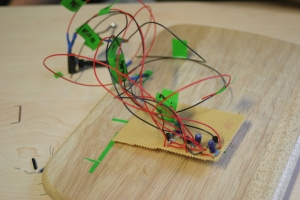
First of all you need to know that the fathers of the almighty MMM are very pro-do-it-yourself, which means that we did not want to use any prewired or ready to use hard- and software, but to build this thing from scratch. Therefore we spent quite some time setting up and soldering down a microphone amplifier derived from here. The amplifier was then connected to a worn out headset microphone.

First Results

First Results

Amplifier

Amplifier

This amplification unit is needed to boost the incoming signal to a level recognizable by the Arduino Uno board – the core of the MMM. The amplification circuit we used was quite sophisticated, incorporating two potentiometers for fine adjustments of gain and amplification levels.

Next up was the speaker – a simple internal PC speaker. After some tests the team realized that the speaker, too, would need some form of amplification to support the high volume level required by the rehearsal room use case. The speaker therefore got its own, admittedly simpler, amplification circuit and a transistor enabling output triggered by the Arduino. The volume control also plugs into this speaker circuit controlling the aforementioned three sound levels.

Speaker

Speaker Circuit

Finally there is the LED-array – four clear light emitting diodes, a white one indicating the first beat and three orange ones for the rest of the beat. The smart reader might recognize the implication of this four-led-flash-beat-thing: it inevitably makes the MMM a rock-metronome!

All these parts are gathered at the heart of our device: the Arduino Uno, which is equipped with a sophisticated state machine, caring for smooth user experience.

The great pitfall

On our engineering journey we encountered one big pitfall that cost us at least one complete workday: a Sharp distance sensor. The background behind this thing is the pervading urge of the MMMs makers to design a whole new metronome experience. What we tried to facilitate was touchless control of the device by enabling gesture based beat recording.

Now what happened is that the aforementioned distance sensor caused so much interference that the microphone amplification unit couldn’t do it’s job anymore, but was biased by a disturbing signal rooted within the Sharp. Finding the source of the interference turned out to be really difficult, since we never worked on such a project before and had minimal electrical engineering background.

Sharp Distance Sensor

The Source Of All Evil

Values and potentials

The multimodal metronome is a gadget designed to simplify a musicians life. It combines the functionality of a beat counter and a metronome and supports beat perception by optical impulses. Therefore it’s main values and potentials lie in the domain of user experience and ease of use. Though, in its current state, the MMM still requires touch input to trigger beat recording, it became clear that with a distance sensor better suited for the purpose this goal is a reachable one. Also the combination of a beat counter and a metronome removes a device from your gig bag. So put together, the MMM resembles a multimodal combination of essential musical tools and helps musicians focus on what they do: keep on rocking!

Next steps

Having achieved the first milestone of a working prototype, the next steps in line involve software optimization, sophisticated, stylish casing and enhancement of the optical output. The basic design sketch also incorporated a led-segment-display showing the current beats per minute – a feature postponed due to time limitations, that can and will be included within the next steps.

Ambient Stack Machine

1 Comment

What is it?

Inspired by the Turing machine described by Alan Turing and other simple computational models like the lambda calculus or rewriting logic we’re providing a simple device that explains theoretical computer models to the normal non-geek guy or gal in an easy to understand and visible way.

Final Presentation

Well, at least that was the idea. The real implementation turned out to be painstakingly difficult, so we settled on something more achievable in the given frame of time: A primitive sorting machine that can separate black and white wooden tokens. The idea behind this was to keep the original plan of the computational machine, while simplifying the software and cutting the necessary hardware in half. The machine in its current state can therefore be seen as a proof of concept that could be connected with an identically manufactured copy of itself, requiring only minimal software changes to simulate simple computational models in a physically observable form.

http://www.veoh.com/swf/webplayer/WebPlayer.swf?version=AFrontend.5.7.0.1281&permalinkId=v22903234KGxeGwHy&player=videodetailsembedded&videoAutoPlay=0&id=anonymous
Watch The Ambient Stack Machine in Tech & Gaming  |  View More Free Videos Online at Veoh.com

How does it work?

In our scenario we’re working with black and white mill stones known from the famous mill board game. The mill stones rotate in a carousel and are being sorted out under certain circumstances. Our very first goal was to just sort out the black mill stones and leave the white ones within the cycle. So how did we accomplish our goal and how does the machine work?

First prototype made out of cardboard

First of all we cut a round perspex plate on where the stones can rotate in a cycle. Several layers of perspex plates follow on top of that, each with a different shape to provide borders and sockets for the rest of the machine to build upon. In order to push the mill stones there’s an electric motor (actually extracted from an old printer) in the center of the platform which drives a small gear on the outside of the machine, which then drives a giant gear in the middle of the plate, thereby transforming the motor’s fast but weak spin into a slow but powerful movement. On top of the bigger gear we’ve installed something like a broom that pushes the stones. We would’ve never thougt that this simple mechanism turned out to be the most time consuming part of our project, but compared to the electronics and the software, the mechanical construction took up most of our time.

The motor spins - but waaay to fast...

But once the carousel was up and running, we needed to figure out the sorting algorithm: In order to remove the appropriate stone from the carousel we labeled every token with QR-Bar-Codes. Then we cut an exit at one point of the perspex plate and placed a web cam over this position. Finally we built a little gate and a kick-mechanism to kick the mill stone through the gate out of the cycle.

Example tokens with QR codes

For instance when a black mill stone comes across the web cam reads the QR-Code, the carousel stops and the kick-meachnism kicks the stone through the open gate. Then the gate closes and the carousel starts rotating again. After a few rounds all black stones are removed and just the white ones remain. As a funny feature we installed a push button known from game shows to be able to start and stop our carousel.

Values and Potentials

While the value of separating white and black tokens may seem dubious at first, the prototype in its current incarnation does indeed offer a lot of potential. It has been proved that the hardest part (the mechanics and general construction) can be made to work, which enables further experiments with the software. The separation of the tokens was the only application that could be implemented in the remaining time after construction, but it should be seen as a placeholder rather than as the final destiny. With the QR code camera recognition and the sorting actuators in place, the machine can after all act like any kind of (primitive) computer. It therefore bridges the gap between the rather theoretical, complex underpinnings of modern software and the physical world. A user could place any sequence of tokens in the loop, which represent functions or instructions from the perspective of the computer. These tokens/instructions are then read and processed by the camera – just like in a real personal computer – but the evaluation of these tokens instructions can be witnessed by the user in a way not possible in circuits.

The machine in action

The possible underlying computational models are many: A primitive stack machine makes a lot of sense, where tokens represent instructions and the sequence of tokens is the computer’s stack. Instructions can then be pushed/popped from the stack until evaluation halts. Another possible model would be term rewriting, where tokens represent mathematical functions and for every turn of the machine one expression is reduced. Such a kind of term rewriting could even explain abstract theoretical concepts like the Y combinator in a fashion that is immediately understandable for non-computer scientists. A computation becomes a form of play where the computer can be influenced by the placement of simple tokens and no syntax error is ever possible.

Next Steps

Even though the mechanics of the machine worked good enough for the final presentation, the most important next step would be a refinement of the whole construction. Less tape and more perspex would enable a construction that is much more solid, durable and most importantly reproducible. With two identical copies of the machine, the original plan of a stack machine / rewriting machine could be turned into reality without “faking” the buffer of unused tokens by manually adding and removing them from the loop. A different software behavior could then easily simulate different kinds of computing metaphors simply by changing the program and using different QR codes.

3D mockup of decorative stack machine

The ultimate goal would be to turn the machine into some kind of an “ambient computer”: A stylish object with changing patterns of wooden tokens in the two loops that would constantly “rewrite” these patterns. An observer could then appreciate the whole mechanism simply for its aesthetics without any knowledge of the correspondence to a real computer. Whenever the observer removes or adds tokens, the pattern would change, sometimes coming to a halt (= the evaluation/rewriting has finished), sometimes changing constantly (= an infinite loop/recursion). The possibility to “look behind the aesthetics” always remains, but the user does not have to. The machine would therefore transform the abstract concepts of theoretical computer science into a form of decorative art and close the chasm between these two seemingly unrelated fields.

Vinyl On The Wall

1 Comment

What is it?

Vinyl On The Wall is a hardware interface for controlling music playback on a home computer. The basic idea behind this widget is to improve accessibility of certain functionality provided by software on desktop machines or laptops. In our case we wanted to work with the way users interact with their digital music collection.

When stored in an application like iTunes, one usually has no choice but to sit in front of their computer to perform changes on the playback. In general, sitting in front of the computer seems something like everyone’s favorite activity nowadays. We just do it all the time. But in fact, noone really wants to sit in front of their computers all the time. It’s uncomfortable, it feels like working, like spending time in the bureau.

So why is everyone doing something they don’t really like? Because they have to. The reason for this dilemma is that a big part of our daily life tasks have moved into the digital world. Mail, Newspaper, Movies, Reading, Phone: it’s all in there. And the access point to this world is the computer.

In consequence, the usability for the different tasks is really weak as there’s only one device for everything. Take music as example: scrolling through a list of endless song names, adjusting the volume by dragging a grey little bar from left to right, clicking on a imaginary window while sitting face to face to a monitor – not very sexy.

Thus, new hardware elements are needed. Hardware that gives decent access to the various functionalities of computers and the online world. Our controller is such an element. Put on a wall it gives access to the playback control of your digital music collection. Besides its functionality, it also comes with a cool design, making it valuable from a trim point of view as well.

Breaking it down to the essence, Vinyl On The Wall could be described as a designer widget for music playback. A cool helper tool to get away from the computer, while still using it.

How does it work?

Our prototype is built out of a few very basic components:

  • Arduino board
  • Stripe of RGB LEDs
  • 3x optical sensor, 1x ultrasound sensor
  • Mechanical engine (taken from a car’s sliding roof)
  • One dusty vinyl record

Put on a piece of wood we connected everything through the Arduino board. The logic compiled on there takes the given sensor input and sets LED feedback and the activity state of the engine accordingly. Additionally, it sends output to a Processing application. From there, the music software controls are set.

Values and Potentials.

There are two main values that come with this project. The first one is its HCI value. As described in the main project description, this widget helps getting away from using the computer in an old fashioned way. Interaction with digital music playback becomes more enjoyable and exciting. The second point is our widget’s design value. Put in a living room it surely will leave an impression on your guests, and of course make you happy as well. Hey, it’s a vinyl on a wall with flashing LED lights. What’s cooler than that?

Next Steps.

Going on with this project it would be interesting to evaluate the controls of our widget. What’s music controls are most needed, how are they best performed with a machine like ours, what additional input could be processed through it. Different sensors could be tested out. The hardware itself is also interesting to think about. What kind of motor would be best to use for turning the record (won’t use sliding roofs no more), or how this widget could be built without the electricity being provided externally. Let’s see where we end up with this one!

This is a project by Daniel Büchele (buechele) and Thomas Bauer (bauerth). If you have any questions don’t hesitate to contact us via @cip.ifi.lmu.de. Thanks for reading through!

Light Mouse

Leave a comment

A project by Xinyao Mao and Leonhard Mertl


What is it?

You’ve surely been walking alone somewhere in the dark, right? Whether it’s outside on a country road, in the cellar or even in your living room at midnight when you grope for the way to the toilet. If you might ever want to be accompanied by someone else, in such a case, our tiny lamp is a walking lamp that lights your way and is there for you as a good listener to your songs and words. It’s a lamp that comes to you, instead of you scrabbling about. It’s your dear fellow that understands your voice and reacts to your hand gestures.

We call it the Light Mouse.


How does it work?

Put the glove on and walk anywhere you like. Meanwhile you sing a deep tone then it’ll follow you. You could bend your wrist to navigate left or right. Once you stop and it runs too far away, you could call it back with a sharp tone. Sing any song you like, just don’t forget to make the tones whether deep or sharp. The Light Mouse can distinguish clearly between low and high voice. We’ve used the open source programming language and integrated development environment “Processing” to separate frequencies of the human voice, so that it could tell the difference between “do, ri, mi, fa, so, la, xi”. So that’s how it works. Without any userguide, you use it intuitively. We’ve implemented the body of the Light Mouse using a radio-controlled car, so that it gets a signal without cable in between.


Values and Potentials.

We’re trying to make our daily equipment as lively as possible. We hope that it serves as a friend more than just a cold machine. As a youth, it dances when you sing. As a grownup, it runs with you. Even when you’re old, it goes together with you to find your glasses or keys. If you’re a girl, you’ll find courage to walk in the dark. If you’re a man, you’ll find it useful to look into each corner of your garage.


Next Steps.

We started at the beginning thinking what kind of things will a person probably do in the dark, especially when someone’s afraid of darkness. People sing songs to get courage and touch with their hands to feel the direction. So we came up with the idea of combining these two common actions. We’re now thinking of using just voices so that the movement could be more natural and vivid. Another question is, how it moves properly? We were hacking a radio-controlled car for the moment because we just got few days, but if time permits, we would surely optimize that. One might imagine a flying Light Mouse, similar to a flying drone. A guard in the dark. A helper at unknown places.

Finally: The Sketchball!

1 Comment

A project by Tom Weber and Daniel Buschek.

What is it?

Our project idea was to develop a spherical plotter, i.e. a device to draw on a sphere. The concept may also be described as a metaphor on pottery making: A rotating “raw” object is altered in appearance by the user’s hands. In comparison to traditional pottery, the Sketchball offers an additional second degree of freedom regarding rotation. Moreover, the user’s hands are not in direct contact with the sphere. However, instead of changing the shape, the artist changes the design or colour of the object.

The following video captures some impressions over the course of the whole project:

How does it work?

The Sketchball concept consists of three basic parts: The ball socket, the drawing arm and the input device. They are described in more detail in the following paragraphs.

Ball base: The socket follows the idea of an “inverted” ball mouse technique. Classical ball mouses use two cylindrical sensors to capture the force of the ball and a third wheel to provide stability. We too use two cylinders and a third passive resting wheel. However, in our project, force is applied the other way round – from cylinder to ball. That way, we are able to rotate the ball so that every possible surface point can be reached by the pen. The pictures below show our first rough sketch and the construction process of these parts.

First sketches

A powered cylinder

Drawing arm: The pen itself is resting on a gallows-like arm and can be raised or lowered down to touch the sphere in changeable intervals. This interval is controlled by physically turning an arrow on a wheel (see final image below). Thus, it is possible to draw full or dotted lines. The arm also applies pressure on the ball from above, using a simple screw with a knob on the end. This ensures that the ball is kept in place and doesn’t “jump” too much from the cylinders, which is important for rather light-weight balls, like polystyrene. The development of this part of the device is pictured below.

Base with arm

Controllable pen

User input: The input device captures the user’s commands, which are expressed with their hands, to follow the pottery-metaphor. Therefore, we created a special pair of cuffs. We first wanted to use bend-sensors on those, but then settled for tilt-sensors instead, because the first were already in use by another group. Therefore, tilting the cuffs is registered by the arduino, which can then send signals to the motors accordingly. Logically, we mapped each glove to one cylinder, so that the user can take influence on the sphere’s rotation in an easy and intuitive way. The image below shows a cuff attached to the rest of the device.

Connecting the input cuffs

Now that all three parts have been presented, the following paragraphs discuss some more details about their construction and implementation.

To power the cylinders, we used two stepping motors. They required a special “motor-shield“, which we assembled and plugged on top of the arduino uno. This shield allowed us to control the steppers rather easily code-wise. However, the shield became quite hot when the motors were running for some time. To counter any possible overheating, we created an active cooling device by glueing a small fan to a short metal pipe-end. This was then used to apply a steady stream of cool air between the motor shield and our own additional “shield” on top of that. This second custom-built shield served as a plug-point for the cuffs and minimized the total space needed for our circuits. The cuffs consisted of the aforementioned tilt sensors, one per glove, and an additional LED to allow for some simple visual indication. Although the LED can be used for to signal anything, in the current implementation it indicates the cuffs’ states (tilted or not).

In our programming we used the AFMotor-Library, which acts as the software counterpart to the motor-shield. With this library, control of a stepper motor can be realized by simply creating a certain motor-object and calling its functions. To sum it up, our program’s main loop reads the input from the cuffs, sets the motors’ speeds accordingly and finally tells the steppers to start turning. The pen is controlled in a similar fashion: Within the loop, the value of the control wheel’s potentiometer is read and administered to the servo motor attached to the pen.

The following graphic pictures the final state of the project, including captions for its various parts. You might want to click on the image to view a larger version.

Final project

Values and Potentials

In its current state, the Sketchball mainly serves artistical purposes. One of its values lies in its ability to provide a rather unusal and unique spherical “3D”-canvas. It has therefore the potential to facilitate the creating of interesting new pieces of art. Moreover, it can be controlled by two users at once (one cuff each), thus offering a possibility for cooperative and communicative design. For example, a ball’s design might be the result of two people shaking hands, dancing and so on. In addition, multiple Sketchballs would have the potential to serve as a new distinct communication device. Just think about a kind of “ball fax”, where one user’s designing actions are recorded and sent to another person for replay. The receiver would then not only be able to recreate the resulting ball, but also relive the sender’s creative process.

For whom is it?

The Sketchball is a creative gadget with a wide range of possible audiences: It can be used by a single person in an “at home” context to create personal gifts, art or decoration. On the other hand, it might also be used as a public interactive installation. In this context, one would typically want to allow multiple people to interact with the device, after another or even at once, creating a ball to represent a group of people, a timespan or something similar. Moreover, art and design related schools, universities or companies may use it as an unusual form of interactive advertisement, maybe on exhibitions. Since the input sensors may be put on other parts of the body as well (feet, legs, …), the Sketchball could also offer a creative outlet for disabled people. Finally, if extended by a high precision plotting/printing head, it could be fitted to produce astronomical models of planets or the like.

Next steps

The current version of the Sketchball could benefit from increasing its power and precision. This would allow to use larger and heavier balls and also enhance the degree of control over the designing process itself. A good first step towards these goals would be to exchange the stepper motors for two similar motors of the exact same type. At the moment, they do not provide exactly the same power. The grip on the cylinders could also be improved with appropriate materials. Some experiments would be required to identify the optimal adherence. With increased precision, it would make sense to develop an action-recording system (see above) to store and replay designs. Further ideas include various switchable colours and finally the mapping and plotting of whole images, received from a computer.

Day 5 (and Day 5,5): The prototypes start to take shape

Leave a comment

After the first steps of progress (and minor setbacks) on Day 4, we devoted another full day to work on our prototypes. Although the air was still full of optimism and passion for the projects, we all realized that more obstacles lay before us than originally anticipated. The reasons ranged from defective electronic components over high precision mechanics problems to the overheating of electronic boards. Thankfully we managed to overcome all these hurdles with lots of different (and often fancy) solutions: While one group adjusted both the audio frequency detection of their algorithm and their own voice pitches, another group started cutting their own gears out of plexiglass.

But not only the hardware turned out to be difficult — the programs soon developed into something much more sophisticated than usual Arduino Sketches: Additional shields such as a stepper motor shields had to be used and programmed, whereas other groups reached for full-blown Processing programs to combine the computing power of a real laptop with the Arduino’s hardware capabilities. Even methods like interrupt-driven programs were considered as solutions for really tricky programming problems.

As the day came to an end, it became clear that some projects were still facing serious issues. More work was needed to get the prototypes into shape for the presentation on Tuesday and some groups started to doubt that Monday and half of Tuesday would be enough to get to that goal. So Hendrik and Sebastian decided to devote half of their Saturday (and therefore their own free time) to further help those of the groups that needed additional resources. The results did not disappoint: After lots of laser-cutting, hardware tinkering and opera-like sound performances (for fine-tuning the audio frequency detection), all of the projects were much closer to completion than before.

Day 4: This is where it starts

Leave a comment

Startup Slideshow

Short one-slide presentations opened the fourth day of the course. Each team had prepared a sketch of their project’s basic concept to show to the others. If you’re interested, you can view them here:

Team 1 | Team 2 | Team 3 | Team 4 | Team 5 | Team 6

Some discussion about what to do first and what could possibly go horribly wrong followed. Luckily enough, it soon became clear that atomic explosions were not to be expected – for now. And that was it with preparation – now let the work begin!

Workshop Workout

The rest of the day we spent working on our circuits, mechanical elements, insanity and so on. Some of us went shopping to get missing parts, some others spread out through the institute’s builduing looking for a drilling machine or whatever vital tool seemed to be severely lacking in existance. Overall, a buzz of creativity sweeped the rooms. It was only broken by (mostly) silent curses, shouted test-activations of audio sensors and the cracking of an old printer being torn apart, salvaging its precious, precious motors. You get the impression.

Resting for now

At the end of the day, several prototypes grew in size, complexity or both. We’re still waiting for that special moment when someone would shout “Eureka!”, but we have already heard a fair share of various non-greek exclamations. A bit worn out, we dropped our soldering irons and laser printers (not literally of course) and let the heat and dust settle in the workshop. Now, to bed, and then: Onwards to the next day!

Video Impressions

Leave a comment

Hey folks,

we’ve been kind of busy the last few days. You know, hacking around, storming the brains out and buying stuff for our projects. But we know it’s cool to look at what we do all day long. So here’s what’s going on:

CUL8A

Brainstorming

Leave a comment

The third day’s topic was all about the means to come up with awesome ideas: Brainstorming!

Having received some basic guidelines on “proper brainstorming” each team was equipped with a poster-sized sheet of paper, some magic markers and post-its. Given this starting situation there was nothing that could keep us from diving into a world of crazy, creative, fantastic – heck, sometimes even a little deviant – ideas and scenarios.

After assembling piles of ideas onto our posters, each team presented their concepts and gathered some feedback to finally be able to face the brutal truth: There can only be one!

So this is what might become real in the foreseeable future:

  • A dice that is thrown by sound
  • A “spheric plotter”
  • A cannon aimed by a sensor glove
  • A multimodal metronome
  • A wall-mounted, circular music controller


Older Entries