The “Real” Dropbox

Leave a comment

The Idea

The Real Dropbox is a interactive scanning device directly connected to the users dropbox account.
Initially the concept suggested further functionality such as implementing the ability to make phone calls using a skype account and a earphone.
The goal was to produce something out of an idea, that could indeed be useful to someone. Even if it was only ourselves.

Bildschirmfoto 2013-08-25 um 16.21.02

The original concept

The Implementation

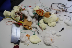
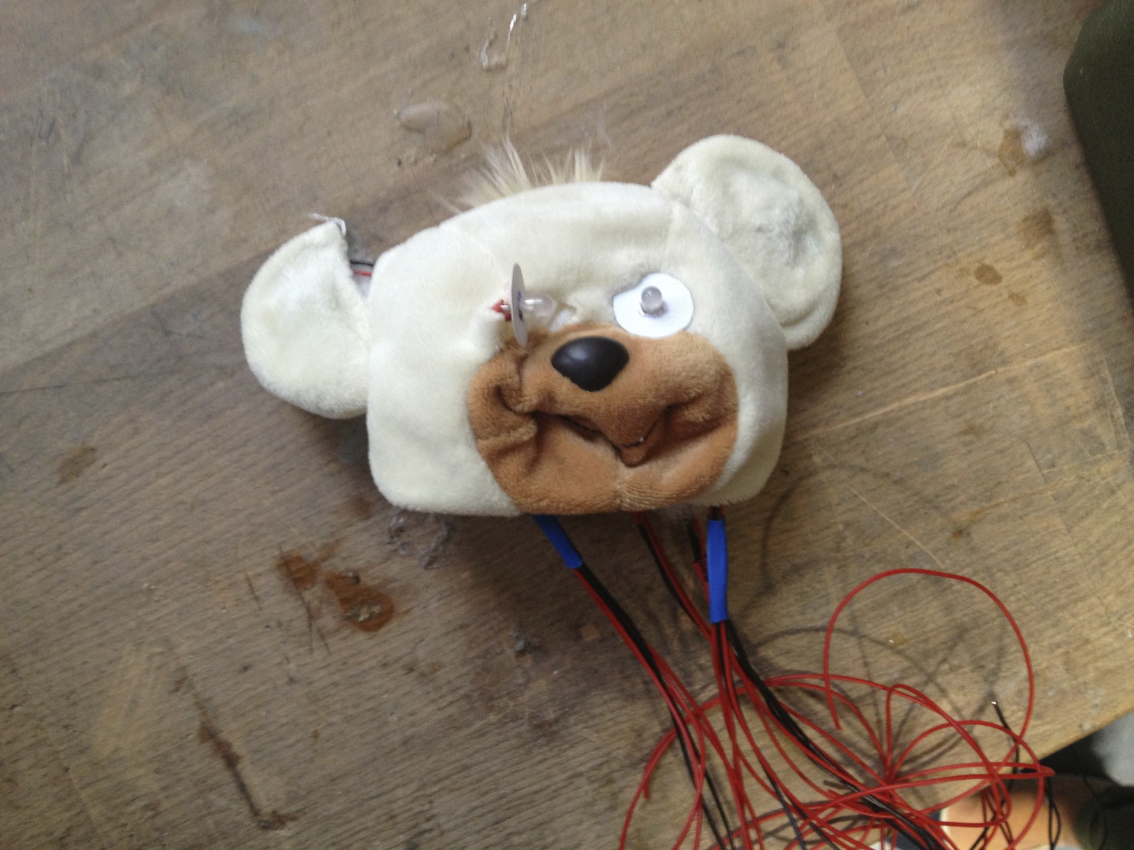
Step 1: Hardware slaughter

The origin was an old multifunctional device from Hewlett-Packard. Our idea was to scan-only, so first of all we needed to get rid of the redundant features. By removing the print framework and keeping only the scanner, we were able to reduce the height of the whole box by multiple centimeters.

2013-08-06 09.51.53

Mess that ol’ thing up

After reaching this first semi-goal without killing the scan function, we went further to the next step: getting the scanner to communicate with the Arduino.

Step 2: Communication via Raspberry Pi

For the idea of automatically scanning and uploading the dropped document, we needed to achieve a well timed communication between all used components. The plan was to aggregate all the required electronic on the inside of the box to build a standalone device, which isn’t visibly connected with other computers. Because the space inside the box was limited, it was impossible to put bigger notebooks in it.
For that reason we decided to use a Raspberry Pi for the communication between scanner and dropbox API, what led us to our first major problem.

Problem #1

Based on a Linux distribution,  we weren’t able to find correct raspberry drivers for our scanner device. Without drivers, there was no chance to interact with the device.  After long research, we admitted our defeat and changed our plans.

Step 2: Communication via Rasperry Pi Windows Computer

After getting caught with this problem for several hours, we finally decided to use the good old-fashioned Windows computer. Required drivers could be found and test scans proved the functionality of both scanner and communication with the computer. Now that we established a connection between scanner and computer, we could begin to explore practical ways to realize our (still theoretical) idea of the real dropbox.

Running the Code

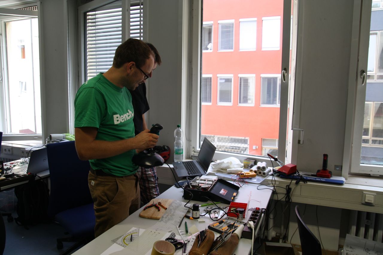
Coding, coding, coding
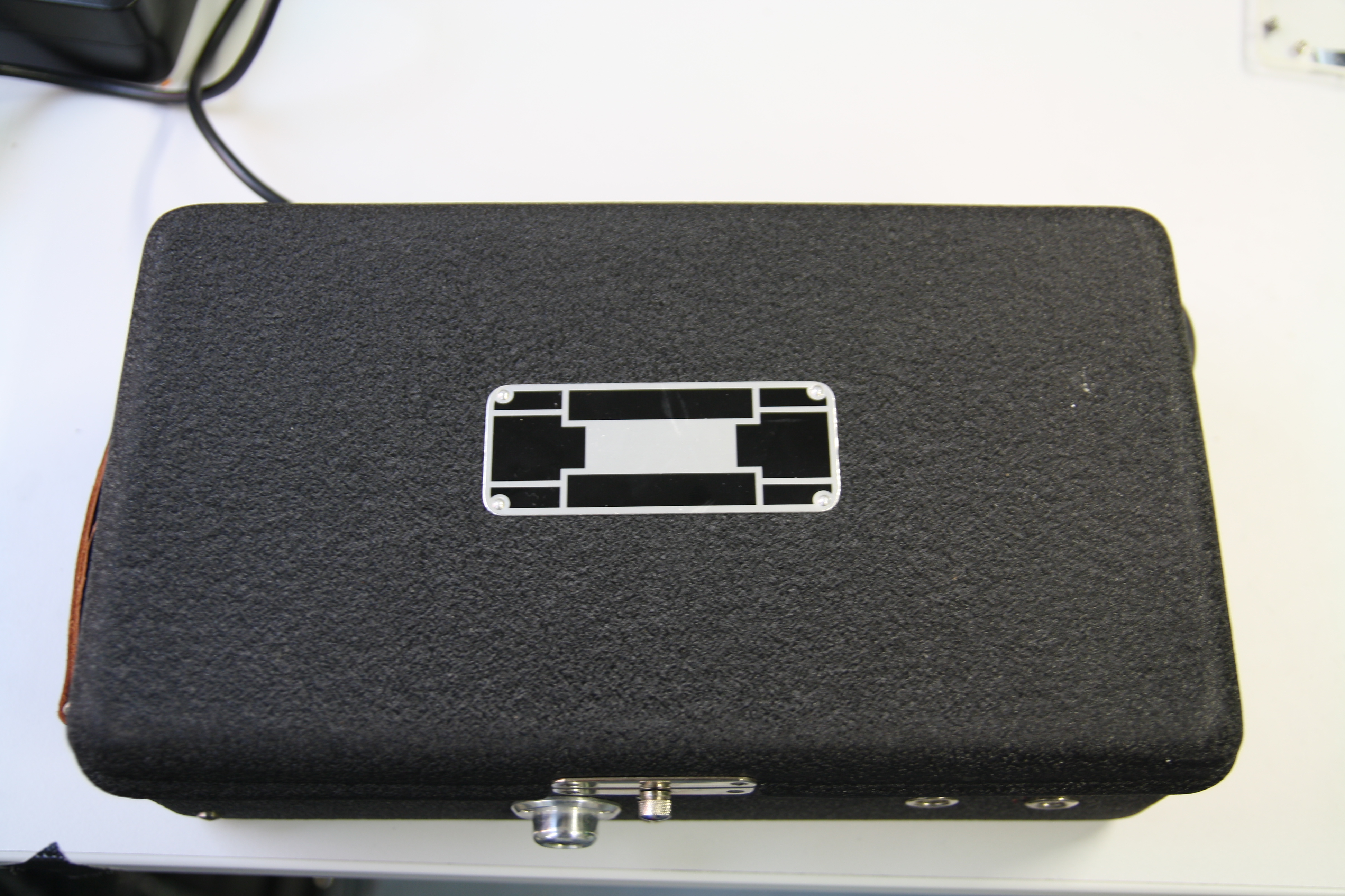
Step 3: The Box

IMG_0027

Integrating the LEDs and wiring up

To create the user’s interaction as easy as possible, weput the whole electronic in a box consisting of acryl glass. This matches the mental model “just putting things into boxes”. Bringing the box to life, we first needed to let the box realize when someone steps infront of it. To reach this goal we built an Infrared Sensor into the front of the box. Two servo motors on the top of the scanner move the lid up- and downwards to enable putting documents in it and close it again to ensure the correct scan process. For the feedback of that scan process, we used LED stripes on the inside of the box.

Step 4: Code, Communication and Connectivity

To make the Arduino, scanner and computer interact, we needed a programming language suitable for this effort. Python became our language of choice.
The communication basically consisted of four parts. The Arduino Code itself to be able to communicate events back and forth between the sensors and python via serial. Secondly we needed a Dropbox registered application with API-Keys to be able to transfer scanned documents directly to the users account. The third part was a shell script executing a .exe runnable to let the scanner do its duty and eventually the python script to glue it all together.

The Interaction

In practice, the user steps infront of the Real Dropbox and (after the IR sensors signal) the servo motors open the lid. All the user’s got to do is dropping his document into the open box and the rest is done automatically. The lid closes and that’s the signal for the scanner to begin. In that state, the LED color changes to blinking yellow giving feedback about the process. After the scanning process is done, the python script enables the dropbox api, so that the scanned .jpeg file is being uploaded into the Dropbox account. After it has been uploaded successfully, the LED change to green, informing the user that the job is done and no errors occured. At the end, the box opens again giving the opportunity to remove the document and then changes the LEDs to blue, which displays that it’s ready for the next scan & upload job.

The final box

The final box

Project Summary

In the end – after a series of failures and frustration in the beginning – the “Real” Dropbox became just the thing we wanted it to be. An easy to use und useful document scanning device. No giggly gadgetry and unneccessary buttons or messages. Our goal was to make things easier and more useful, providing an easy option for people who just want to burn their paper mess at home and have it available wherever they go, without having to buy a new Device, but instead upcycle their old scanners from home.

The story of DJ Teddy

Leave a comment

Fulfilling this year’s topic “Reuse, Reduce, Recycle” we searched for some old, used stuff and found three things: An old teddy to reuse, a shopworn MP3-Player to recycle and finally (to reduce the amount of junk in our homes ;-)) an unused step machine, but what to do with those parts? Our first thoughts were “everybody likes music, everybody loves teddies and of course everybody would go crazy seeing his teddy dancing to his favourite music while motivating him with a step machine”. So our idea was born, a music playing teddy or as we named it: “DJ Teddy”. Some additional special effects should allow it to become the perfect entertainer on every party. In the end the final result surprised us and I promise, it will surprise you, too, but more on this later. The next step was brainstorming our idea and designing a first concept.

Brainstorming

Brainstorming

Concept

The mp3 player should be controlled by interactions with our teddy. For keeping the handling nice and easy, we had to focus on the basic functions “next”, “previous”, “change volume” and “play/pause”. The head is the main part of controlling.

The theory

The theory

By pressing an ear you can switch to the next or previous song. We kept the standard order of the buttons, so that left ear means previous and right ear next song. To play or pause the music you need to push his nose. The eyes should be LEDs displaying the current playing status. When music is played they become green, when the music stops they glow red. DJ Teddy’s belly button is misused to change the volume by turning it. In order to make it a real party gadget, we added the ability to dance to music by moving his arms and a heart that blinks to your steps on the step machine! The music comes out of his feet. Let’s see how we realised it.

Realisation

Step 1: Preparing the teddy

First of all we needed to cut our teddy into pieces and rip the inside out. That sounds cruel and yes, it was! Our beloved teddy transformed into some dead parts of cloth. We took off the legs, the arms, the head and the ears, so that we could fill it with electronic and wires.

Step 1: Preparation

Preparation

Step 2: Hacking the MP3 player

This step was the most complicated and took us a lot of time. After we removed the casing and mechanical buttons, there were two possibilities to control the MP3 player:

  1. Connect two wires to a mechanical button and solder them to a button at the mp3 player to bridge it. Then connect the arduino to the mechanical button to read when it is pressed. Repeat this for each button on the mp3 player. Now the arduino recognizes when a button is pressed and is able to handle this information in its program in order to light the eyes and move the arms.
  2. This time instead of mechanical buttons we use transistors as electronic switches. We connect each of the MP3 player’s buttons to a transistor that is controlled by our arduino. The microcontroller is now able to “push” the buttons by switching the transistor with a controlling signal. Mechanical buttons are only needed to get the user’s input.

In the first possibility the music would be controlled by mechanical buttons and not by the arduino, that’s why we wanted to use the second one. The advantage here is that the program decides how to handle the inputs and when to push the buttons at the MP3 player.

In the following picture you can see the circuit for one single mp3 player button. Again we need to bridge the button with two wires (1). The red wire goes to the arduino’s 5V pin, the black one to the transistor (2). Because this is a NPN transistor, we have to connect it to ground. Finally the blue wire goes out of pin 13 (3), which we defined as a digital output pin, over a resistor into the transistor’s base and works as a control signal. To push the button our program just needs to write a digital “HIGH” to pin 13. As long as there is a HIGH signal at the transistor’s base, the mp3 player button is pressed. To release it, we have to write “LOW” to pin 13.

MP3 player hack

MP3 player hack

Unfortunately, we killed two MP3 players with this circuit and lost a lot of time. We had to start from the beginning again and again, so that we finally decided to use possibility 1.

Step 3: Make it move, add LEDs and integrate loudspeakers

Now we replaced the eyes with LEDs to display the playing status as I described at the beginning. Our program listens to the nose-play-button, so that it knows when the music is playing. Using two RGB-LEDs we can change the colour as we want to. More difficult was the construction to allow DJ Teddy to move his arms. A hemisphere of plastic fills the teddy’s chest. In it there is a servo with strings connected to the arms. When the servo rotates, the strings of each arm are pulled alternately, so that the arms move up and down.

Step 3: Insert the electronics

Insert the electronics

Then we connected little loudspeakers (taken from a radio) to a 3.5 mm phone connector that fits into the player’s headphones plug. At this point the music volume was very low, even on the maximum setting. That’s why we disassembled some old loudspeakers with an integrated amplifier, which we built into the teddy’s stomach.

To sum up DJ Teddy’s condition:

  • Buttons in the ears and in the nose
  • RGB-LEDs in the eyes
  • Plastic hemisphere with a servo in the chest
  • Strings in the arms
  • An amplifier in the stomach
  • Loudspeakers in the feet

What is missing? Right! Literally the heart of our teddy.

Step 4: Let the heart glow by using the step machine

As mentioned earlier, we wanted to use a step machine that makes our heart glow. Therefore we used a sliding potentiometer which changes the resistance when someone pushes down the right or the left side of the step machine. The arduino reads the values as an analog input and dims or lights red LEDs which are arranged in a heart shape.

Step 4: The step machine

Step 4: The step machine

Presentation

In the end we only had to reassemble the whole package and… oh wait, the time is gone! As I told you in step 2, we spent a lot of time killing mp3 players. Now we had to present our project and it looked horrible. It worked, but it looked like a teddy dying in a car accident with his entrails scattered all over the table. So we came up with an idea: “It’s not a bug, it’s a feature”. When it was our turn to present our project, we told the audience DJ Teddy died and came back as… Teddy Zombie! Cloth organs, ketchup blood and a giant saw helped us to sell our project as a successfully finished zombie project.

Zombie Teddy

Zombie Teddy

Lessons learned:

  1. Never give up your project
  2. Zombie teddies still smile

Video

Melody Bakery

Leave a comment

1

This project, “Melody Bakery”, was made from an old toaster. We equipped it with an Arduino Mega, took advantage of the toaster’s convenient, useful physique and transformed it into something totally different with completely new functionalities: A MIDI sequencer loop station, aka. “Melody Bakery”. This device can read a set of eight notes, making up two four-four times at the range of seven notes adding up to one whole octave. Furthermore, you can feed the toaster with a set of an instrument which the notes are to be played with and a background beat to make the produced music loop more enjoyable and usable for playing along with e.g. the bass or the guitar. The notes, instrument, and background loop can then be sent to an audio program on a connected PC.

Idea

2

The idea for this project came into existence when we found this old, non-functioning toaster. Since it didn’t toast bread properly any more, it could no longer be used for its original purpose. However, we agreed that it would have been a pity to throw it out. Therefore, we decided to bring back some live to this toaster again. The motto of this year’s course “reuse, reduce, recycle” supported our idea: To disassemble the toaster and rebuild it as something completely new. Since both our team members play several instruments as amateur musicians, we decided to create a device that has something to do with music and can be used, for example for practicing playing the guitar. In the end, we came up with a midi sequencer loop station that can read notes written on the toaster’s crumb tray.

 4  3


Concept

From the beginning on, we tried to keep the basic concept of the toaster, where you put something into the toaster’s slots and then start a process by pressing down the handle.

5

Instead of putting bread into the toaster’s slots, we defined one slot as input for the instrument that the notes should be played with, the other slot was destined to serve as input for the background loop sound. For the notes themselves to be recorded, we used the crumb tray at the bottom of the toaster as a note sheet, and magnets on top of the crumb tray as notes. This way, we have a removable note sheet where notes can easily be added, removed, or modified by moving the magnets on the trays top surface. To scan the notes on top of the note sheet, the crumb tray simply has to be pushed into the toaster.

When everything is set, the toaster’s handle can be pressed down, which starts the MIDI-transfer of the notes, instrument, and background loop to an audio program on a PC connected via USB.

Let’s get technical!

The note sheet & note scanner

Let’s start with the feature of our “Midi Toaster” that required by far the most effort.

We decided to read the notes by taking advantage of the fact that white surfaces reflect light a lot better than black ones. Therefore, we painted the toaster’s crumb tray black to serve as the note sheet. Then we put a matrix of white spots on the top of the black tray, where each spot represents one note. One dimension (vertical) serves as the tone pitch and the other one (horizontal) for the temporal distance of the notes. While the first seven light sensors’ job is to read the notes, the eighth light sensor is to read the music’s beat. To make the notes easy to modify, we used small magnets that we covered with white duct tape instead of directly painting the notes onto the tray. This way, you can create a new melody simply by sliding the magnets on top of the tray’s surface.

With a distance of about 1-2 cm above the crumb tray, we attached eight light sensors and eight LEDs inside the tray’s slot. Each light sensor is being backlit by its own LED, which is positioned right next to the sensor. Whenever a white magnet note is positioned right underneath a sensor while slowly pushing the crumb tray into the toaster, the light reflected is a lot higher compared to the light reflected by the dark crumb tray. This way, it was possible to recognize a note as such to be recorded. It was necessary to measure and find the light threshold, above which a spot underneath a light sensor can be recognized as being white.

6  7 8  9

10

While pushing the tray into the toaster, the key to getting good results for the note detection was finding the best possible threshold for each individual light sensor. Different light situations forced us to find a more flexible solution than manually calibrating each light sensor in the source code. Therefore, we decided to implement a calibrate button in our toaster, which measures the brightness of the black tray without any white spots underneath. This helped a lot for our goal of making the scanner accurate enough not to skip any notes or not to see notes where there actually are none (e.g. when the light sensor on position three measures a value, it is influenced by the light reflected from neighboring notes on position two and four. In this case, light sensor number three should not deliver a false positive value).

11

Inside our toaster, an Arduino microcontroller functions as its heart and brain. Every LED, sensor and button is connected to one of its pins. Due to the high number of required analog pins for our project, we had to use Arduino Uno’s bigger brother, an Arduino Mega.

12The logic the Arduino Mega runs is declared in our program written in C, which turned out to be around 600 lines of code. One of our program’s responsibility is to transfer the recognized notes, instrument, and loop sound into MIDI signals and send them to an audio program on a PC connected via USB.

Instruments and background loops:

13The realization of adding different instruments and background loops was relatively straight forward. We used some card board toasts that we designed in Adobe Illustrator and cut with a laser, and attached some copper bands at different positions at the bottom. When inserted into the toaster’s slots, each toast closes different contacts with their copper bands and therefore can be recognized as different instruments and loop sounds.

Some of our problems and how we solved them:

Finding the right threshold for the light sensors:

Finding the best threshold for every light sensor for recognizing the notes was by far the hardest part of our project.

In the beginning, we planned on making it possible to scan 16 notes on the note sheet. This lead to several misinterpretations of notes by the light sensors. Some notes were skipped and others were read where there actually was just a note on its neighboring position. We then decided to half the number of notes on the note sheet to only eight notes. This lead to much better scanning results. An auto calibration button on the toaster, which we implemented during our testing period, helped a lot for detecting the right note values. Another measure we took in order to get better results while reading the notes was to increase the amount of LEDs lighting up the crumb tray. We doubled the amount from originally four to eight LEDs, so that in the end each light sensor had its own LED.

The toaster’s handle:

When pressing down the handle of the toaster to start the recording, it has to be held down by a magnet until the recording is done. To do so, we had to replace the original magnet which operated with 220 Volts by a magnet that can function with only 5 Volts, as this is the maximum current we can receive from our PC’s USB slot.

This step was unexpected for us and turned out to be quite time-consuming until the magnet held the handle in place just right.

MIDI-Transfer

Unfortunately, we had to find out that the Arduino can not directly send MIDI-signals via USB. Therefore, we had to order a MIDI-to-USB-adapter online. Luckily, this adapter cable could be purchased pretty cheap and the delivery only took less than a day..

14

Reuse, Reduce, Recycle – Gameboy 0.5 beta

Leave a comment

“Reuse, Reduce, Recycle”

was the general topic for this semesters Sketching with Hardware course, so first of all, we needed something to work with. It was pretty clear that it would be most fun to take an old thing – whatever it would be – and make it behave in an unusual way. Luckily, we found this at a flea market:

IMG_5052_farbabgleich

It says oscilloscope on it and was once used in medicine for graphing the human pulse. The oscilloscope consists of two main parts, the left side holding a revolving paper roll, a spring and mechanics to move the paper stripe.

IMG_5124

On the right side, we find two moving arms with small containers for ink at their ends. Each is mounted onto a box that contains an axis which turns in response to small changes in pressure. Tubes connect the box to a cuff and a switch allows the user to select into which box the air flows.

What did we make out of it?

IMG_5417

“Gameboy 0.5 beta” – our idea of how gaming might have looked 100 years ago. We built an arcade game for the advanced. You don’t play one level, you play two. At the same time. With a joystick. The two needles are arranged vertically, so the game is split into an upper level and a lower level. The upper level is always the same, collect the golden coins by going over them and loose one each time you crash into a wall. The y-axis if the joystick directly maps to the position of the needle.

For the lower level, we offer two modes, one of them is basically the same as on the top, so we use the x-axis of the joystick to set the distance between the needles. The second one is inspired by jump and run games, you try to avoid running into boxes by jumping. Once you have jumped, you need to wait until you touch the ground before you can jump again. After completing the level, unfortunately you need to count the score yourself. Which is easy because you left an ink line, see?

IMG_5399

How does it work?

Let us first say what we did not change: We saw the beautiful mechanics that power the paper roll and quickly decided to leave that complete part untouched. We replaced the original black cover with a transparent one so you can see the wheels turning while playing.

IMG_5154

Apart from that though, we changed most parts. All the tubes had to go and the mechanics in the pressure-sensitive boxes were replaced by servo motors. These
enable us to directly control where the needles point. An arduino receives the input from the joystick and translates it into angles for the servos,

depending on the mode.  The mode can be changed with the knob that originally directed the air flow (POS. 1 or POS. 2).

IMG_5053

Another thing we changed are the needles. Since we could not find ink that worked with the original ones (picture above), we use the tips of edding rollers that are attached to laser-cut arrows.

Technical stuff

This is how the components are put together. The weird thing in the bottom right corner is the joystick ;).

Joystick_Steuerung_Steckplatine

How do we get the joystick input values? – We use an old joystick that has a GamePort-plug, so the arduino 5V is on pin 1, pins 3 and 6 are both wired through a potentiometer in the joystick. The arduinos analog inputs can now measure the incoming voltages for both x- and y-axis. Our code automatically calibrates the center position – the specification says the resistance should vary between 0 and 100000 Ohms but of course, that is not even close to reality.

Where does the power come from? – The arduino delivers enough power to run the servos and the LED. A hole in the box can be used for a USB plug, but we have a 9V battery connector inside as well.

How are the servos held in the boxes? – Mostly glue and some paper to keep the right distance.

How are the servos connected to the axes? – Again, glue. Actually, we broke the original axes and mounts, so we use parts of an old umbrella instead. The moving arms are held by magnets. That allows us to remove them whenever they run out of ink.

How much does it cost? – The oscillograph was 4€, the joystick 0,5€. All other material was already present. We were, however, quite lucky with the oscillograph, there is one on ebay for 60€ at the moment.

Demo

If you want to play yourself, you will be able to do so at the Media Informatics Open Lab Day this fall. If you only want to see it in action, check out the video!


Thanks

to Sebastian LöhmannBernhard Slawik and Frederick Brudy for their help throughout the course!

Walkman Remote

Leave a comment

Reuse, Reduce, Recycle → Upcycle

This year’s workshop theme was “Reuse, Reduce, Recycle”. So basically the idea is to create new devices that use parts of or consist of electronic scrap. Another interesting idea is to upcycle things. Upcycling takes old items and enhances them in some way, either by improving purpose or by getting it all in a whole new context. So we searched basements, drawers, boxes, flea markets and the internet to find stuff that could be fun hacking.

Idea

The idea we have chosen for our project started with a walkman: many of us have one at home and it is hard to throw it away, because it often has good childhood memories attached to it. On the other side a walkman has all controls that are needed to control a music player (Play/Pause, Next/Previous Song, etc.) so our plan was set: let’s build a remote for your computer’s music player that is inside an old walkman. It should contain all the basic functions needed for that: play/pause a song, switch between songs and adjust the volume.

Initial Idea.

Initial Idea.

Our basic idea impressed the participants and the persons in charge the most among all of our ideas we presented on Day 3. So in the brainstorming session we refined our expectations on the prototype and developed further ideas that could be implemented within the small case of the walkman. Some of these creative new facts were to turn the remote in a music streaming device, adding a sleep time or even fitting the whole setup in a cassette (this idea is further explained in the last section of the post). After the creative part of the brainstorming and the presentation of our poster we got to the point of considering technical issues and what can be realised within such a small box casing.

Results of our first brainstorming.

Results of our first brainstorming.

After we first wanted to create our own infrared sender to copy the signals sent out by an Apple remote, the other participants hinted that a wireless connection can be done by hacking yet another keyboard, but this time with a bluetooth sender. More technical issues were discussed like what kind of buttons could be used to trigger commands, how the device could be supplied with power and if the connection between the remote and the computer should be uni- or bi-directional. Having clarified the technical setup we had to obtain all parts we needed. Our shopping list contained a bluetooth keyboard and a bluetooth adapter for headphones. We found the most important part, our walkman, on eBay. A very friendly old man was giving it away for free and as he was located within a half an hour bike ride, we had everything we needed for the project ready.

Getting Started

Similar to the exercise of Day 1 we decided to hack a keyboard controller. As our remote should be wireless we got a bluetooth keyboard and disassembled its controller. Our next objective was to find out the pin combinations for all the keys we needed. We used a systematic approach so that we could easily remember and note pin combinations.

Approaching pin combinations systematically.

Approaching pin combinations systematically.

In the progress of our project a major issue of the keyboard hack was that the media keys of the keyboard and the shortcuts to control the computer’s music player can only be fired by connecting a combination of key-pairs (e.g. Fn + F8). One way to achieve this would be to permanently activate the Fn key. This solution was however not satisfying to us as it would mean that the bluetooth controller permanently fires this key, possibly reducing battery life. Our second approach was to connect the pin combinations for both keys simultaneously via transistors. After some unsuccessful attempts we found out that this approach works, but requires good timing: if the time interval between both keys was a bit to big, the combination was not triggered. Firing the function key a bit longer than the modifier key (as you do with a real keyboard) worked perfectly.

First steps: speaking to Spotify through an Arduino.

First steps: speaking to Spotify through an Arduino.

Stripping the Walkman

When we first opened the case of our walkman, we were pretty impressed. It contained a board with loads of capacitors, switches, resistors and mainly everything that is need for radio reception. The soldering joints looked crafted. There was a lot of manpower involved when the device was built back in the last century. Under that board a lot of mechanics revealed that we needed to dismount in most parts. After a session of screwing, cutting and removing parts the case was finally stripped to its bare minimum.

First looks at the walkman's inside.

First looks at the walkman’s interior.

How does it work?

Our device contains a bluetooth keyboard controller that can trigger certain keys when the right pins are connected through a power circuit. In some cases (like the play/pause key) we could directly close the power circuit by mechanical movement of the walkman’s buttons. In other cases where key combinations and software logic were needed (like the text-to-speech feature) we used the Arduino to close the circuits programatically by setting transistors to high and low.

Major components: 9V battery, Arduino Uno, soldered board with transistors, bluetooth controller.

Major components: 9V battery, Arduino Uno, soldered board with transistors, bluetooth controller.

Bluetooth controller with first wires soldered onto it.

Bluetooth controller with first wires soldered onto it.

Arduino Uno hooked up to bluetooth controller, buttons and transistors.

Arduino Uno hooked up to bluetooth controller, buttons and transistors.

The power supply is a 9V block battery that is connected to a switch which closes the circuit to the Arduino. With the Arduino being powered we could also supply the keyboard controller with its 3,3 V output. The bluetooth adapter for the headphones can be connected by turning it on in the cassette case.

On the software side of the project we needed Arduino code to evaluate control input values and to trigger key combinations by controlling transistors. Furthermore some scripts on the computer enable us to define the output of the key combinations sent from the walkman’s bluetooth. Thus the project is not fixed to controlling a certain music player, like Spotify, as we can change the commands with our script. Additionally we created AppleScripts which allow to change the computer’s audio output device (between line-out and bluetooth headset) and to parse the currently playing song for text-to-speech.

AppleScript which parses and speaks the current song.

AppleScript which parses and speaks the current song.

Challenges

The biggest challenge for the project was to always keep an eye on the limited space the walkman offers. The very first step was to get rid of all unnecessary parts inside. Then we had to plan, where to place the bluetooth keyboard controller, the Arduino and the bluetooth headset adapter. Available space was further constrained by our wish to have an all wireless self-contained prototype which meant that place for a relatively big 9V battery was needed. Even though it was dimensioned for two AA batteries, we fortunately managed to fit our 9V block into the original walkman battery slot with some force and a rather big saw.

One solution to save space would have been to switch form our Arduino Uno to a smaller version, the Arduino Mini. This one has no USB connection so it can only be programmed via an additional programmer module. In our considerations we got to the point that the Arduino Uno could perfectly fit at a certain spot in the Walkman’s case and so we decided to focus on getting the rest of our work done first.

Another challenge was to tell apart all the different wires. As we expected to have a big chaotic bundle of wires packed in the small box casing in the end, we started to colour-code each wire depending on its function early on. That way it was relatively easy to connect the correct wires in the final phase.

Final Prototype

Final Prototype

Going one step further

An ongoing idea from this project is to scale down all of the functional parts of the device so that it could fit in a simple audio cassette. That way every unused cassette player could be upcycled to a music player remote simply by inserting the cassette.

Thomas Burghart and Maximilian Walker
{lastname}@cip.ifi.lmu.de

The Workout Orb

Leave a comment

General description The Workout Orb (formerly: Weather Orb Muscle Cool Trainer) is a device that allows you to keep track of the progress in your workout (such as lifting weights) as well as to improve its quality. It consists of a wristband worn near the elbow that measures the rotation and muscle activity of ones arm. It then sends this data to the Arduino and thus triggers the feedback in the second component, the actual orb. This component cosists of a translucent orb that is filled with water, which, when turned on, is nebulized to form mist. It is then illuminated by LEDs to give visual feedback. The orb also harbors a small piezo element that additionally allows feedback in the form of sounds an melodies. input deviceThe Workout Orb Ideation process The concept for The Workout Orb is based on two of our original ideas, first a wearable gesture interface and second a weather simulator orb. Having originally decided on the weather simulator we then used brainstorming techniques to further elaborate on this idea. ideation processIdeation process – from ideas to final concept During this process we decided that having an output device would not be satisfactory. To create a direct interaction we were looking for an interesting input device. The decision to use the orb as a tool to improve ones workout was made by being inspired by another group that tried to utilize a workout stepper as in input device. Since this device was not available for our group, we thought about an alternative way measuring workout / muscle activity. Through further brainstorming and lots of trial and error the exact details for our project formed very much on the go and in response to problems that we found. Functionality Inside the wristband three contacts that are part of an Electromyography (EMG) sensor that connect to ones skin to measure muscle activity. A gyroscope, to measure xyz movement of the arm, is also implemented. These sensors in combination give access to information on when your arm moves in which direction and most importantly with what kind of intensity and effort. The built wristband is comparable with the MYO (https://www.thalmic.com/myo/) input device, which will be hopefully released in the near future. 😉 input deviceThe wristband – our input device Analyzing this data, meaning the timing, duration and direction of ones lifting weights is assessed and then visualized via coloured LEDs inside the Orb. After successfully finishing the workout session a set of lifts a short jingle and a light pattern are played to indicate the completion. To optimize performance The Workout Orb also evaluates the positioning of the lifting arm and thus can detect whether the exercise is performed in a way that is beneficial or warns with an acoustic signal when you start making movements that may have a negative effect on your training of even health. Components and inner workings Hardware Input The wristband as actually a recycled headband that is shortened to half size. As already stated, the input interface consist of two different kinds of sensors, an EMG sensor and a Gyroscope (not shown on the picture below). Compared to the upcoming MYO our wristband was not wireless and required a special power-supply with a positive and a negative voltage. Thus of a lack of money we utilized two ordinary 12V supplies to also create a negative potential. Armband Internal ComponentsComponents of the armband. There are two actual sensors, which are attached on a particular muscle that has to be measured and a third sensor (the reference sensor), attached to a bony part of the arm to calculate the relative change. Output The Orb is build from a plastic sphere mounted onto the base of a former lava lamp (the remains of which are used as weight for testing). Inside a laser-cut piece of acrylic holds the LEDs and the vaporizer. Orb - InsidesThe insides of the orb Since both of the components, LEDs and vaporizer, require more than the 5V the Arduino offers, they are connected to transistors on the breadboard to use an external power supply. Those transistors are then controlled by the Arduino which, for reasons of water-proofness is located outside (and preferably far away from the orb). The Arduino connections furthermore contains resistors with the intend of preventing voltage leakage from the transistor that might give the LEDs unwanted colours (which happened a lot during early testing). Next to the breadboard there is also a piezo element inside the base to provide audio-feedback slightly amplified by the metal casing as a resonating body. Circuit layout - Output DeviceCircuit layout of the output device. Software Input The event that triggers a successfully performed movement is detected by a deflection of the delta value in muscle activity. Additionally the delta values of a gyroscope are used to detect if the movement is also performed in the right direction. The sensor processing is taking place on the Arduino micro controller itself. Furthermore the sensor raw data and the sensors delta values are transmitted via USB to the computer, where our own software visualizes these in graphs. This software also allows the user to set their own arm and hand gestures to a free chose able function. The setup is simple: The user can assign a key to a desired gesture, that he is able to record. After saving it, the computer tries to find the recorded pattern in the current sensor data. sensor dataRepresentation of the sensor data, later to be processed and visualized in the orb. Output To assess the progress of the workout the Arduino internally differentiates 256 states of training process which in turn also provide (with a little math) the the LEDs brightness to form red light at the beginning gradually turning yellow and then green upon completion. To control how many exercises have to be made to complete one workout set, the speed, i.e. the value added per exercise, can be varied. The so generated colour is then flashed every time the motion is detected, gradually fading away in a simple loop. Upon reaching state 255 (or more) the piezo element is triggered using the already existing code for playing sounds´which we modified to play something that seemed slightly more appropriate than Happy Birthday or Super Mario music. Encountered problems Two occurences can be counted as the major challenges faced troughout the construction of The Workout Orb. The first being the matter of sensor data classification. This describes the process of taking the raw sensor data, identifying  the desired patterns and consistently responding to them. The second challenge was that of regulating the power supply for all components. Since all elements (except for the piezo acutator and the Arduino itself) required at least 12 V, some 24 V, extensive use of transistors had to be made. However these proved to be unreliable and often didn’t cut power entirely when they were supposed to. Varying designs using resistors were tested that ultimately provided satisfactory but not optimal results. Another minor challenge in this field was the fact that some transistors died on us due to the heat while soldering.

We however mastered all these challenges and were able to present a working prototype that not only proved to be a good learning experience but might also be a glimpse into the future and the possible uses for the MYO released end of this year and other gesture interfaces.

Day 7: Final Sprint

Leave a comment

IMG_5305

So there we were. Three o’clock in the morning. Two teams left. The deadline breathing down our necks. But surrender? In no possible way. Although thoughts and actions had become significantly slower, we kept focused – after all we had enough food supplies (in form of bananas, cereal bars, pizza left-overs and cookies) and the will to finish what we had begun was unbroken. And so we soldered, coded, composed and stitched throughout the whole night until the first beams of sun started to come through munich’s rooftops.

IMG_5303

It was just at that time, when when we had reached our low point. But in the nick of time the other teams should arrive and give us new hope. Well rested and highly motivated they entered the course room at about nine o’clock and spread a vibe of optimism and vigor. And so everybody rolled up one’s sleeves for the final sprint.

IMG_5325

And so it was no surprise that almost every team had finished their project in time when at 1 pm it was about time for the final presentation. Friends, researchers and and department employees got a short introduction into the topic and afterwards the teams presented their final prototypes (videos coming soon).

IMG_5344

After every prototype had been inspected and checked out and all questions had been answered, there was only one task left – cleaning up the mess. And so every wire, every resistor, every LED, every motor, every sensor end every arduino was collected, sorted by type, length or color and stored away. But just until next year, when the next twelve students are about to learn how to sketch with hardware…

IMG_5413

Day 6: The Panic Level

Leave a comment

The last full day for our projects. Somehow the presentation on friday came to everyone’s mind more and more. Some teams were affected by this thought more than others. The following post will show the progressing “Panic Level” measured throughout they whole day.

9:00 AM: Let’s get started

Team 1: They took their toaster back home for some fine-tuning. At the lab these improvements should be tested. Also toast was laser cut.

Image

Yummy!
Toast!

Team 2: Working with another mp3-Player and sewing the poor bears wounds.

Team 3: Getting the last needed switch from the old walkman to work and communicate with the Arduino.

Team 4: Everything technical is working fine. What to do? Develop some funny and entertaining game modes.

Team 5: Finishing the case of the dropbox and finally get on with the logic programmed for the Arduino.

Team 6: One person coding and the other building a case for the Arduino below the ORB they seem pretty relaxed.

Image

Light it!

11:30 AM: First results of the day

Team 1: A method for calibrating the breadcrumb drawer is being developed. Meanwhile the MIDI transmission goes on.

Team 2: Frustrated at the moment -> no comments given

Team 3: Working on closing circuits via Arduino.

Image

Loads of wires for a small walkman

Team 4: Two game modes have been developed and multiple levels are designed by hand.

Image

Sebastian is already testing the game

Team 5: The box case is finished. Hardware and core features work. Yay!

Team 6: Sensor classification on the one hand and updating the output device on the other one.

2:30 PM: After the lunch break

Image

Countdown

Team 1: Reading spots in the breadcrumb drawer works and it is auto-calibrated at the start. Also functionality to the buttons of the toaster should be added.

Team 2: Another mp3-Player down. (The third?), at least the teddy’s movement is progressing.

Team 3: Toggling keyboard shortcuts with Arduino and transistors.

Team 4: Still working on new levels. Can’t wait to play.

Team 5: The box is working and the plexiglass will be layered. As everything works smooth LED lighting is planned.

Image

Pretty acryl box

Team 6: The input sensors are ready and software is coded. Meanwhile the output device’s contacts are being re-soldered.

6 PM: Most other project days were over by that time

Team 1: The calibrating method is being improved and a MIDI cable is integrated in the project.

Image

Under the toaster’s surface

Team 2: The mp3-Players audio signal is strengthened for better output quality. Next project step is to integrate the stepper with the teddy bear.

Image

Teddy Head

Team 3: Starting to solder everything together, a lot of wires indeed. Thanks to color-coded wires one could keep track of what to connect.

Team 4: After everything worked some problems with the servo motors aroused. Working hard on fixing them.

Team 5: The LED lighting is in progress. The box is coming alive.

Team 6: Changing the LED colours for different settings.


Early at night: Who needs sleep?

Team 1: Getting food and trunks to be prepared for a long night.

Team 2: ” ” ” ” ” ” “

Image

Teddy ❤

Team 3: Big soldering session.

Image

Walkman wired

Team 4: The team has left to buy some new servos and save energy for the last final hours on Day 7.

Team 5: Bringing the box to life. Maybe making sounds?

Image

Turn the lights on

Team 6: Bernhard commented on the team’s status: “Dichter und Denker”

The Panic Level

Image

The evolution of the “Panic Level” curve clearly shows some changes throughout the day. But it gives proof that all teams worked hard on their projects and didn’t give up. The end of the day hints: Everything will be fine for the presentation.

Day 5: Making progress!

Leave a comment

Day 5 was all about turning gathered ideas into reality. Every team seemed very concentrated on their tasks and with every accomplished intermediate goal the number of wires, devices and code lines steadily increased. After a fresh, pleasant morning, hot temperatures came back as usual and made every available fan spinning. The working area spread out to the 2nd story as more and more components and tools (like the laser cutter) were needed.

Team 1: Turning breadcrumbs into music

“Team Toaster” accomplished quite a lot today. While tracking contact of toasts being inserted in the toaster appeared to be more problematic as assumed, big progress could be made with the light sensors in the bottom of the toaster. After some calibration and writing the software light and dark spots on the breadcrumb drawer (those will later correspond to musical notation) could be recognised by the Arduino successfully. Communication via midi is now possible.

Contacts inside the toaster.

Contacts inside the toaster.

Turning "breadcrumbs" into musical notation with an Arduino.

Turning “breadcrumbs” into musical notation with an Arduino.

Team 2: Can’t stop me!

“Team Teddybear” was hit by one of those technical problems that take as long to fix as to discover in the first place: without any visible indication their MP3-Player (which plays a major role in the whole setup) suddenly died. However, after spotting the problem a replacement and a pragmatic solution could be found. The rest of the day lots of wires were soldered and attached to the teddybear which is also increasingly packed with buttons and LEDs.

Wiring up speakers and MP3-Player.

Wiring-up speakers and MP3-Player.

Wiring up ad teddybear (this will look cute eventually).

Wiring-up a teddybear (this will look cute eventually).

Team 3: Keep it vintage!

“Team Walkman” advanced toward their goal from both, hard- and software side, today. Scripts to control the computer’s bluetooth and text-to-speech and Arduino code for the communication to the keyboard controller and shake gestures were written. After some struggle with a built-in potentiometer from the 70s, some new buttons were added to the plastic enclosure while (of course) keeping the vintage look. As in the previous days it was time to plan the inner life of the walkman very precisely. Every millimeter counts!

Speaking to Spotify through an Arduino and Bluetooth

Speaking to Spotify through an Arduino.

Work in progress: Arduino, Bluetooth Controller, Walkman board and lots of wires.

Work in progress: Arduino, Bluetooth Controller, Walkman board and lots of wires.

Team 4: Electric ink

“Team Oscillograph” made further progress in gaining control of the complicated mechanics and programming the Arduino. A big challenge lied in “reading” the ink, which should ideally conduct electricity. Different kinds of ink were tried and different solutions were discussed. This prototype remains very exciting!

Casing of the oscillograph.

Casing of the oscillograph.

Lines and fascinating mechanics.

Lines and fascinating mechanics.

Team 5: Heavy lifting

“Team Dropbox” was all about motors and sophisticated mechanics today. After experimenting with different step motors which continually ran out of breath, big success was made with servo motors. These tiny things can now open a huge box over some attached threads when activated by a (infrared) light barrier. They also managed to scan images with a Python script, to take one stop further to Dropbox integration.

Opening a huge box with a tiny motor.

Opening a huge box with a tiny motor.

Taking photos with this scanner now works!

Taking photos with this scanner now works!

Team 6: Muscles and Fishbowls

“Team Orb” divided their work in input and output tasks to advance quickly: the (arm) muscle interface was improved so that the input data can now be passed to Processing where muscle tension and arm movements are displayed. The next task here is to classify data patterns to recognise characteristic arm and hand gestures. The output side of the prototype involves fluids so that the team’s workspace was frequently extended to the bathroom or other places with water supply. The lava lamp turned out to not do the job, so a fishbowl is now in the field. It was successfully equipped with lights and a vapor generator and even by now it looks great!

Muscle tension and arm movements mapped to curves in Processing.

Muscle tension and arm movements mapped to curves in Processing.

Lights in a fishbowl, soon also equipped with a vapor generator.

Lights in a fishbowl, soon also equipped with a vapor generator.

Day 4: Let’s build ’em prototypes!

Leave a comment

As of day four, the time has come for the six teams to rack their brains about fiddling around with the prototypes using the ideas gathered through the brainstorming sessions the week before. The sun, still pounding its seemingly endless heat into our lab, was only partly repressed by installing and building our own fans (why not use our newly gained know-how?)  🙂

However, the heat couldn’t impede our evolving progress on the prototypes:

Team 1: Mastering the Solderings

Working on their digital audio workstation and music sheet reader, a lot of soldering for the light sensors had to be done.

Throughout the day, this task has been accomplished with great satisfaction. Also, after some smaller obstacles with a magnetic fixture for the toaster handle, there have been great results with the light sensors and cable spaghetti management.

Image

Result of the day: Light sensors, LEDs and nice cablework.

Image

Light sensors, LEDs and Arduino attached to the Midi-Toaster

Sarcastic yet humorous comments from our team lead like “You like to switch the negative and positive pole, don’t you?”, “Some electrical shock could be a good lesson” didn’t spoil the moods. 🙂

Team 2: Mutilate that Teddy Bear!

For a cyborg teddy to be born, it first had to be sliced into pieces.

While it seemed that today’s birthday girl had lots of fun chopping off that teddy’s head and pinching out its eyes in order to fill it with electronics, some problems also emerged. Hacking an old mp3-player’s buttons turned out to be easier said than done: finding the right current and producing good sound proved to be quite strenuous. Towards the end of the day, however, starting and stopping the mp3-player via pressure sensors was already possible.

Having to spend her birthday in the lab, she let her aggressions out on the poor teddy bear

Having to spend her birthday in the lab, she decided to let her aggressions out on the poor teddy bear

Teddy-Splatter!

Teddy-Splatter!


Team 3: Microengineering

Team “Walkman remote” now rustled up some sickly looking vintage Walkman. After disassembly, there has been a lot of struggling trying to fit all necessary components and cables into its relatively tiny case. Furthermore, translating the Walkman’s buttons and switches to address Arduino’s logic showed to be kind of a hassle.

Vintage Walkman

Vintage Walkman

Trying to get all up and running with Arduino

Trying to get all up and running with Arduino

Team 4: Refunctioning an Oscillograph

In order for their old oscillograph to reveal its great, gear filled look inside the case, team 4 decided to design and laser cut some acrylic glass to a new, now transparent part of the chassis. Requiring 4 attempts to do so, this design task turned out to be the main focus point of the day. After all the trouble, it showed to be worth the effort. Furthermore, it is now possible to control the newly attached servomotors through the connected joystick.

A sketch for the new chassis part to be laser cut

A sketch for the new chassis part to be laser cut

Controlling the servomotors in the oscillograph with a joystick

Controlling the servomotors in the oscillograph with a joystick

Team 5: Raspberry vs Windows; Python vs. Team 5!

Bright prospects in the morning: Authentification and uploading files on dropbox through a Python script works!

Since Arduino Uno is not quite capable of handling all the data coming from a scanner, its competition “Raspberry Pi” was to take its place. After quite a while of installing Raspbian, this slim Debian derivate disappointed by lacking support for the scanner. Therefore, good ol’ Windows XP on an Eee-PC had to do the job.

Afterwards, the wrestle with necessary Python modules, their different required Python versions and promising though non functioning “Easy-Easy Installers” from the depths of the WWW took the rest of the day until 7:30 pm.

Software installing sessions

Software installing sessions

Having Raspberry up and running

Having Raspbian up and running

Team 6: Fully Charged Capacitor + Curious Adrenalin Junkie = Sensational Short

Capacitor 1 :  0 Student.

This big capacitor definitely won one curious student’s respect today. While experimenting with this at first seemingly harmless piece of electronic in order to get the flashgun to work, the capacitor impressed by creating its own noisy flash when shorted. 🙂

Besides making this involuntary experience with electrical shorts, a lava lamp has been boiled and disassembled, and an accelerometer and an EMG-chip have successfully been soldered and addressed for the arm muscle tension-measuring wristband.

Fun with the evil capacitor

Fun with the evil capacitor

Trying the EMG-Chip for the Wristband

Trying the EMG-Chip for the Wristband

Older Entries