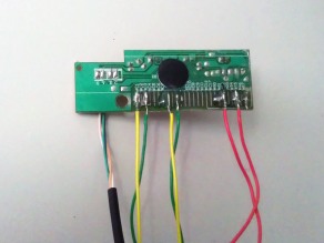
Hardware Hacks: Servo Hacking

Leave a comment

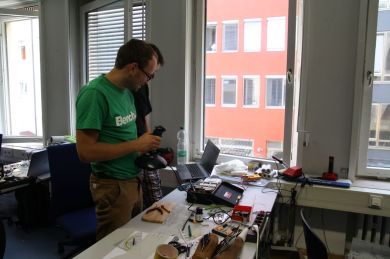
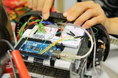
For some reason many people – even computer science students – are originally afraid of unscrewing and opening electrical devices. While it is truly not recommendable while said device is currently under charge I believe it provides a lot of general understanding on how a device works and also enhances the learning process. Things get less abstract when we understand HOW. It makes us think of the WHY and why not to make it better. So put your fears aside and just start to unscrew something. Something not too expensive so you don’t have to worry about messing up too much. Something that will be useful if you unscrew and modify it for example. A Servo for example.

A Servo is some little device that can turn something around, but only to and from a certain angle (ca. 90°). But if you want a Merry-Go-Round you will have to get rid of the block. So they work like this:


Here is how to:

First off: There are several versions of servos. Each one more difficult to hack:

  • 100% plastic servos – the easiest to hack
  • Plastic servos with a metal potentiometer – hackable with a small workaround
  • Metal servos: The whole gear-work plus potentiometer are made of metal – if you cannot work an angle grinder, forget it.

I’m going to describe how to hack the first and second one as they are the ones we usually use at Sketching with Hardware.

So let’s get started.

First a little overview of the innards of a servo:

http://www.jameco.com/Jameco/workshop/howitworks/how-servo-motors-work.html

A look inside a servo

If you hack a servo there are basically two things you have to do:

  1. Remove the stopper so the gears can turn 360°. This is usually positioned on the drive gear with the output spline.
  2. Modify the potentiometer – output spline connection so that the potentiometer is fixated but the output spline can still turn.

So now we can start: unscrew the servo. But keep the side with the output spline up. Otherwise the gears may fall out! Don’t worry about the motor and control circuit falling out on the other side. They are fastened really well.

After opening the servo you’ll find an armada of gearwheels. I truly recommend you now make a photo from at least two angles (up and side) so you know how to put it back together – as there are small variations on the gearwheel allocation between the different models. Now look closely at the gearwheels (you have to take them out) one has a plastic plug over some gearwheels. This is the stopper. Use a cutting pliers to remove it.

In some cases there are no gearwheels where the stopper has been. If you are very sure in its use use the bandsaw to add them manually otherwise ask somebody who does or look for a servo that does not require this step!

With the gearwheels now capable of turning 360° we can move to the next step: The potentiometer

Now first a little explanation about how the motor and potentiometer work together: The motor is able to go around infinitely, but is stopped by the potentiometer that can only go 90°. They are connected by gearwheels. The motor drives the gears who are controlled by the potentiometer. The potentiometer can only turn on a 90° radius. On the potentiometer the output spline is mounted. That in turn is the key to turning the servo arms.

What we know now: the motor does not turn the output spline directly, but connects to the gears that do. Unfortunately those gears are connected to the potentiometer with a pin. But we do not want the potentiometer to influence our movements.

The solution is rather easy: you have to drill a hole in the output spline where the potentiometer pin goes in. You basically just drill out the thread (dt. Gewinde). I recommend using a steel drill and it will go through like butter. Also take care not to screw the vice too tight or you damage the gears. Putting some cardboard between the vice and gear helps.

Finally: Fixating the potentiometer

The potentiometer turned to one side gives full power. Turned completely to the other side it turns the power off. Best thing would be to keep it in the middle (or at highest if you require it) to test the current setting you can use an LCR-meter.

You now have to fixate the position of the potentiometer. Otherwise you risk that it moves to the “power-off” state sometime later. For that last step you can try to somehow glue it. With the plastic versions I was very successful using the hot glue gun. Although you risk getting a few minor burns on your fingers while molding it. After applying the hot glue let it cool down. Then cut the protruding hot glue away with a Stanley knife (horizontally, or you draw the glue back out). For the metal  potentiometer the hot glue does not work really well, but I did not have the time for further materials science. If you find something better that hot glue for those, please share and post your results in the comments.

And that’s it. Congratulations! You just hacked a servo.

Day 6: The Panic Level

Leave a comment

The last full day for our projects. Somehow the presentation on friday came to everyone’s mind more and more. Some teams were affected by this thought more than others. The following post will show the progressing “Panic Level” measured throughout they whole day.

9:00 AM: Let’s get started

Team 1: They took their toaster back home for some fine-tuning. At the lab these improvements should be tested. Also toast was laser cut.

Image

Yummy!
Toast!

Team 2: Working with another mp3-Player and sewing the poor bears wounds.

Team 3: Getting the last needed switch from the old walkman to work and communicate with the Arduino.

Team 4: Everything technical is working fine. What to do? Develop some funny and entertaining game modes.

Team 5: Finishing the case of the dropbox and finally get on with the logic programmed for the Arduino.

Team 6: One person coding and the other building a case for the Arduino below the ORB they seem pretty relaxed.

Image

Light it!

11:30 AM: First results of the day

Team 1: A method for calibrating the breadcrumb drawer is being developed. Meanwhile the MIDI transmission goes on.

Team 2: Frustrated at the moment -> no comments given

Team 3: Working on closing circuits via Arduino.

Image

Loads of wires for a small walkman

Team 4: Two game modes have been developed and multiple levels are designed by hand.

Image

Sebastian is already testing the game

Team 5: The box case is finished. Hardware and core features work. Yay!

Team 6: Sensor classification on the one hand and updating the output device on the other one.

2:30 PM: After the lunch break

Image

Countdown

Team 1: Reading spots in the breadcrumb drawer works and it is auto-calibrated at the start. Also functionality to the buttons of the toaster should be added.

Team 2: Another mp3-Player down. (The third?), at least the teddy’s movement is progressing.

Team 3: Toggling keyboard shortcuts with Arduino and transistors.

Team 4: Still working on new levels. Can’t wait to play.

Team 5: The box is working and the plexiglass will be layered. As everything works smooth LED lighting is planned.

Image

Pretty acryl box

Team 6: The input sensors are ready and software is coded. Meanwhile the output device’s contacts are being re-soldered.

6 PM: Most other project days were over by that time

Team 1: The calibrating method is being improved and a MIDI cable is integrated in the project.

Image

Under the toaster’s surface

Team 2: The mp3-Players audio signal is strengthened for better output quality. Next project step is to integrate the stepper with the teddy bear.

Image

Teddy Head

Team 3: Starting to solder everything together, a lot of wires indeed. Thanks to color-coded wires one could keep track of what to connect.

Team 4: After everything worked some problems with the servo motors aroused. Working hard on fixing them.

Team 5: The LED lighting is in progress. The box is coming alive.

Team 6: Changing the LED colours for different settings.


Early at night: Who needs sleep?

Team 1: Getting food and trunks to be prepared for a long night.

Team 2: ” ” ” ” ” ” “

Image

Teddy ❤

Team 3: Big soldering session.

Image

Walkman wired

Team 4: The team has left to buy some new servos and save energy for the last final hours on Day 7.

Team 5: Bringing the box to life. Maybe making sounds?

Image

Turn the lights on

Team 6: Bernhard commented on the team’s status: “Dichter und Denker”

The Panic Level

Image

The evolution of the “Panic Level” curve clearly shows some changes throughout the day. But it gives proof that all teams worked hard on their projects and didn’t give up. The end of the day hints: Everything will be fine for the presentation.

Day 4: Let’s build ’em prototypes!

Leave a comment

As of day four, the time has come for the six teams to rack their brains about fiddling around with the prototypes using the ideas gathered through the brainstorming sessions the week before. The sun, still pounding its seemingly endless heat into our lab, was only partly repressed by installing and building our own fans (why not use our newly gained know-how?)  🙂

However, the heat couldn’t impede our evolving progress on the prototypes:

Team 1: Mastering the Solderings

Working on their digital audio workstation and music sheet reader, a lot of soldering for the light sensors had to be done.

Throughout the day, this task has been accomplished with great satisfaction. Also, after some smaller obstacles with a magnetic fixture for the toaster handle, there have been great results with the light sensors and cable spaghetti management.

Image

Result of the day: Light sensors, LEDs and nice cablework.

Image

Light sensors, LEDs and Arduino attached to the Midi-Toaster

Sarcastic yet humorous comments from our team lead like “You like to switch the negative and positive pole, don’t you?”, “Some electrical shock could be a good lesson” didn’t spoil the moods. 🙂

Team 2: Mutilate that Teddy Bear!

For a cyborg teddy to be born, it first had to be sliced into pieces.

While it seemed that today’s birthday girl had lots of fun chopping off that teddy’s head and pinching out its eyes in order to fill it with electronics, some problems also emerged. Hacking an old mp3-player’s buttons turned out to be easier said than done: finding the right current and producing good sound proved to be quite strenuous. Towards the end of the day, however, starting and stopping the mp3-player via pressure sensors was already possible.

Having to spend her birthday in the lab, she let her aggressions out on the poor teddy bear

Having to spend her birthday in the lab, she decided to let her aggressions out on the poor teddy bear

Teddy-Splatter!

Teddy-Splatter!


Team 3: Microengineering

Team “Walkman remote” now rustled up some sickly looking vintage Walkman. After disassembly, there has been a lot of struggling trying to fit all necessary components and cables into its relatively tiny case. Furthermore, translating the Walkman’s buttons and switches to address Arduino’s logic showed to be kind of a hassle.

Vintage Walkman

Vintage Walkman

Trying to get all up and running with Arduino

Trying to get all up and running with Arduino

Team 4: Refunctioning an Oscillograph

In order for their old oscillograph to reveal its great, gear filled look inside the case, team 4 decided to design and laser cut some acrylic glass to a new, now transparent part of the chassis. Requiring 4 attempts to do so, this design task turned out to be the main focus point of the day. After all the trouble, it showed to be worth the effort. Furthermore, it is now possible to control the newly attached servomotors through the connected joystick.

A sketch for the new chassis part to be laser cut

A sketch for the new chassis part to be laser cut

Controlling the servomotors in the oscillograph with a joystick

Controlling the servomotors in the oscillograph with a joystick

Team 5: Raspberry vs Windows; Python vs. Team 5!

Bright prospects in the morning: Authentification and uploading files on dropbox through a Python script works!

Since Arduino Uno is not quite capable of handling all the data coming from a scanner, its competition “Raspberry Pi” was to take its place. After quite a while of installing Raspbian, this slim Debian derivate disappointed by lacking support for the scanner. Therefore, good ol’ Windows XP on an Eee-PC had to do the job.

Afterwards, the wrestle with necessary Python modules, their different required Python versions and promising though non functioning “Easy-Easy Installers” from the depths of the WWW took the rest of the day until 7:30 pm.

Software installing sessions

Software installing sessions

Having Raspberry up and running

Having Raspbian up and running

Team 6: Fully Charged Capacitor + Curious Adrenalin Junkie = Sensational Short

Capacitor 1 :  0 Student.

This big capacitor definitely won one curious student’s respect today. While experimenting with this at first seemingly harmless piece of electronic in order to get the flashgun to work, the capacitor impressed by creating its own noisy flash when shorted. 🙂

Besides making this involuntary experience with electrical shorts, a lava lamp has been boiled and disassembled, and an accelerometer and an EMG-chip have successfully been soldered and addressed for the arm muscle tension-measuring wristband.

Fun with the evil capacitor

Fun with the evil capacitor

Trying the EMG-Chip for the Wristband

Trying the EMG-Chip for the Wristband

Day 1

Leave a comment

Welcome to Sketching with Hardware in summer term 2013!

Our first day started out with a very basic introduction to electrical engineering (resistors, capacitors, switches) and was followed by a rather weird team-finding process.  When everybody had found their partner-animal by imitating said animals noise (or mating call?), we were ready to go. First exercises included the multimeter, soldering and LEDs, so we were prepared for the afternoon session.

After lunch, it was time for the fun part. Each team was given a keyboard, which would then be torn apart carefully disassembled. The component we looked for was the controller. It connects the keys to the computer via USB and allowed us to generate inputs in other ways than typing a key. The teams then chose a simple game and built a custom controller for it:

Team 1:

Robot Unicorn Attack – Jump to jump and shoot stars by shaking the thing in your hand. Whatever that thing was…

IMG_4908

Team 2:

Racing game: A styrofoam steering wheel and the accelerator pedal built from a keyboard package guarantee the ultimate racing feeling.

IMG_4960

Team 3:

Pong for feet: Why use your hands for playing pong?

IMG_4966

Team 4:

Play curvefever with your keyboards package instead of the keyboard!

IMG_4906

Team 5:

A recycled joystick for racing, made of whatever was left, including a drain pipe…

IMG_4978

Team 6:

Wireless ball game – shoot a penalty with a real ball. Bluetooth keyboard hack and self coded game!

IMG_4989

Day 1

Leave a comment

First day of the Sketching with Hardware practical course. When the advisors had introduced themselves and some formalities were settled, we started with the basics of electrical engineering. First, we approached the physical relationships between resistance, current and voltage. Then electrical circuits and their components were explained in more detail.
Once the most relevant components and their usage were illustrated, it came to hands-on testing. Armed with a multimeter, we proceeded to measure voltages and resistances and checked connections for continuity.
Based on this basic knowledge we constructed simple circuits on breadboards on our own. Equipped with battery, jumpers, resistors, diodes, switches, buttons and capacitors, we applied the previously learned contents practically.

Following the lunch break the course continued very practically. A keyboard controller extracted from a computer keyboard served as a starting point for small group work. The goal was to design a creative way of interaction for computer games. The concept was to short two contacts of the keyboard controller to send a specific signal to the computer. After we found out what contacts corresponded to which key on the keyboard (e.g. the arrow keys) we could replace these by self-designed switches.

ImageImageImage

Gunslinger. Because getting up is just too hard.

Leave a comment

What is it?

Some people have a really hard time waking up and getting out of bed everyday (including us). To ensure that they won’t be late for work or class people have found their solutions to themselves out of bed. Some use more than one alarm clock and others even place their alarm clock into the bathroom, so they can immediately take their ice-cold wake-up-shower. But what if the alarm clock is too quiet and overheard? Catastrophe. Worry no more, dear friend: the Gunslinger Alarm Clock is here. This baby will get you out of bed faster than you can say “What-the-hell-is-happening-and-how-do-I-make-this-thing-stop?”.

First, you choose when you’d like to wake up just as with any other alarm clock. Once the alarm starts at the chosen time, the Gunslinger Alarm Clock then uses its gun to shoot a rather tiny ball through the bedroom that is needed to turn off the tremendously loud alarm. That means you have to get up and go look for it, and trust us – you will! If you want to speed up the searching process, the gun can be aimed at a particular point in your room, otherwise the position can be randomized.

How does it work?

The gun can perform two basic movements to aim: it can turn 180 degrees left-to-right and 120 degrees up and down. For that, you can use your computer mouse or a touchpad to precisely get the position you need. Before you can set the alarm (or shoot the gun), it is necessary to properly load it. The loading process stretches a spring inside the gun barrel. We chose a strong spring with a resistive force of 60 Newtons – so the ball can be shot through very large bedrooms, too. In order to compress that particular spring, we built-in a strong motor that has a bolt-on screw. This screw is attached to a carriage that moves the spring backwards. After a certain point, the trigger is automatically locked and the motor moves the loading contraption back to its initial point. You can see what happens inside in the hand-sketch picture.

Sketch of the gun's interior

The gun can be triggered both automatically (when the alarm starts) or manually (to have some fun at the office). The triggering is indicated by playing a shoot-sound.

For the alarm clock, a standard digital alarm clock was hacked. Once you have found the ball, insert it into the clock and a switch will shut it off.

In case you want to build your own Gunslinger gun, here are the ingredients:

  • 2 big servo motors to control the horizontal and vertical gun position
  • 1 smaller servo motor to trigger the gun
  • a powerful motor that can go clockwise or counterclockwise to compress the spring
  • a lot of metal parts (gun barrel, trigger, bolts)
  • a stable stand. We built ours with a laser cutter.
  • last but not least, an Arduino to control the gun.

This slideshow requires JavaScript.

Values and Potentials.

Our gun alarm clock helps people get up and thus prevents from oversleeping. In our idea-finding process we tried to find out what problems any person has each day and this is what we came up with. Potentially, our prototype could use paint balls or water filled balls that are shot at the sleeper. Because some people are likely to overhear their alarm clock even it is standing in the closest proximity. Of course, one would have to use very small projectiles to make sure no one gets hurt. We want to help people, not hurt them.

Next Steps.

There are a few things that could enhance the Gunslinger Alarm Clock experience even more. So far, we have not developed a snooze function. We thought the snooze button could randomize the gun position and further compress the spring. Alternatively, the gun could be equipped with an automatic re-load mechanism: If the person decides to snooze, but the ball has already been shot, the alarm can be turned off and the gun loads another ball by its own.

Additionally, the design is still prototypical. The exterior has some rough edges and the overall look can be improved. In manual mode, it would be cool to have LEDs indicating the loading status.

About

The Gunslinger Alarm Clock project was carried out by Andreas Kolb and Tobias Stockinger. We’d like to thank our tutors Hendrik and Sebastian for the awesome course!

Day 1: Electronic Basics and Keyboard Hacking

Leave a comment

Getting excited

Monday 9 a.m. – the best time and day to start off this practical course with an introduction to electronics. Sebastian and Hendrik explained the most basic parts and concepts to give us some fundamental knowledge for the upcoming tinkering. We learned about current, resistors, LEDs, transistors, Ohm’s law and so on. After that, the fun part started when we received some basic soldering training and learned how to apply a multimeter to measure various parameters. Unfortunately, the need for coffee could not be measured precisely by that device.

Keyboard Hacking

After lunch, we began hacking keyboards: By opening the backs of the brand new devices and removing unnecessary parts in an unscrupulous act, we salvaged the main component, the control unit. Modifying these control units allowed us to send input manually to the connected computers, using several new and rather unusual interaction methods.  The main topic for this modification task was the idea of creating a new “game controller”. So we teamed up in groups of two, following probably THE most ridiculous way to find the partner: draw a card from a hat and make the sound of the animal that’s written on that very card. This actually happened and we can prove it whenever necessary. So the groups and gave new life to the poor little keyboards that we tore apart like a hungry lion hunting down a gnu. Some of the results are shown in the pictures below.

In general, no special preparations were made for this task. Apart from the keyboards, we just used what was available from the institute’s tremendous pool of parts, known to some as the chamber of horrors.
While the design wasn’t the primary goal and pretty much reminded of traditional gamepads, some ideas didn’t rely on moving within a game via ordinary buttons, but instead by tilting the device. This feature was enabled through the use of super-awesome “ball switches“. On top of that, buttons triggered special actions like shooting. One group added a foot-pedal as well, to take the player’s game experience to a higher level for a racing game – pedal to the metal and Mario Kart was pwnd.
Another group created their own game, using contacts attached to the floor and one foot of the player. It was therefore possible to detect real jumps. The challenge of the game then was to achieve the longest “air time” possible (by this point, you might have noticed the pic with the one guy walking on air. Don’t worry – he eventually came down and did not have to stay up there).
A cool concept was created for a balancing game: Here, the controller most closely resembled the actual appearance of the game itself where the player would stand upon a simple seesaw-like balancing board, which could then be rocked from one side to the other to keep several balls from falling off a shifting wooden plank within the game. N1.

See ya tomorrow

At the end of this first day we have already gained some general experience with creating and modifying electronic devices. Overall, the idea of “sketching” became clearly visible, which is fundamental to this course. Always remember, kids: We are not here to develop highly refined products, but prototypes – or, well, sketches. Hacking a keyboard gave us a good first impression of what this means, but we bet there’s a lot more to come.

Hacking a USB keyboard

Leave a comment

For the practical part of the first day every group gets a package containing a multimeter, a soldering iron, a side cutter, screwdrivers, LEDs, resistors, all kinds of other handy electronic toys the core part of our future projects: the Arduino Uno Board (http://www.arduino.cc/)

Equipped with those essentials tools we are ready for the first practical task of the day. To learn the handling of the multimeter and the soldering iron, we are asked to measure the resistance of different resistors and afterwards solder it to a board.

The afternoon challenge is to hack a USB keyboard and transform it into any game controller we can think of. Every team therefor chooses a computer game and develops its own individual game controller. But first, we need to learn how to hack a USB Keyboard…

Hacking a USB keyboard

There are various descriptions and tutorials, how to hack a keyboard on the Internet. Arduino offers a very nice German tutorial that explains all the steps in detail. http://www.arduino-tutorial.de/2010/06/keyboardhack/

In the following you find a short description of the single steps:

Step 1: Open up the keyboard

First we need to remove all screws at the back and open up the keyboard. To hack a keyboard we need the controller of the keyboard. It is practical to use hot-melt glue to fix the fragile parts (cables) of the controller and make sure that the controller doesn’t get damaged when it is taken out.

At the bottom of the controller plate is a number of connection pads. If there is contact finish on the pads, we need to remove it with a small piece of sandpaper to make sure that we can solder cable tails to it later.

Step 2: Trace the letters back to the pins

Every controller is different. Therefore it is necessary to test the pin configuration. This can be done by using the sheets with the conductive tracings of the keyboard and a multimeter. We connect one end of the multimeter to the key that we want to use and test the ends at the controller for a signal.

Step 3: Attaching wires and

Now we can solder wires to the chosen pins and connect them to any kind of sensor, switch or whatever else you can think of…

Keyboard Hacks of each group:

Group A:

Anna Follmann, Beatrix Vad

Game Controller – Super Cruiser

Super Cruiser is a kind of wheel. You can control a game, for example a Race Game by tilting it to any side. Tilt it to the front to accelerate, tilt right or left to change your direction.

Technically it is realized with three Ball-Switches. The Button on the top works with copper band and a feather which was unter the Enter Key of the keyboard.

Group B:

Johannes Preis, Chadly Marouane

Game Controller – Jump & Run

This Game Controller for Jump & Run games, brings the feeling of Jumping to the real world. Each time the user want the player to jump he has also to jump.

A cardboard lying on the floor detects if the user touches it. If not he is probably jumping. With a stick you can control the running direction of the player.

Group C:

Verena Lerch, Frederick Brudy

Game Controller – Fire Joystick

With the Fire Joystick you can control various games. You can change your direction with tilting the joystick. For firing/hitting or any other game action you can use the button on directly on the joystick or hitting a button on the floor with your foot.

This Controller works also with Ball switches to detect inclination. The Buttons a build with copper band.

Group D:

Maraike Stuffler, Robert Rödler

Game Controller – Kung Fu Fighter

Kung Fu Fighter is a fighting game. The player can hit with his fists or with his feet. Exactly this realizes the Kung Fu Fighter Game Controller. You can hit a cardboard with your fists and one with your feet. To run through the game world you turn a pice of plastic to the right or left.

The cardboard buttons are realized with two peaces of cardboard with a little bit of space in between.On each side there is a copper band. When the two copper bands touch each other the button fires. The controller for running uses ball swiches.

Group E:

Kyun-Jing Park, Lorenz Schauer

Game Controller – Air Joystick

The Air Joystick is like a normal Game-Joystick but without a base. It has a button on the top for interaction with a game.

This Joystick has an very special Button on the top. It uses the conductivity of a human finger. When the user touches the top of the joystick, he closes an electric circuit.

Group F:

Verena Hillgärtner, Bernhard Hering

Music Instrument – Music fist

Music fist is a music interface for a computer. You can use it with a software keyboard that matches keyboard inputs to MIDI signals. By turning your arm around you can change the tone. With the buttons on the top of the instrument you can decide if you play or not.

The selection of the tones is realized with 8 ball switches. Ball switches only switch when there is an inclination modification by 45 degrees. So this tool uses two struggles with 4 ball switches. You can switch between these struggles with the 3 different buttons on the top.