GPS Box

Leave a comment

When thinking of outdoors, one of the first things that came into our minds was GPS. We use it nearly constantly in our everyday activities – from locating your own position to finding the right directions to your goal. From this concept an idea started to form, and soon the GPS box was born.

What is it?

A box with a secret locked inside. The only way to reveal it is to bring the box to a specific location. Only then will the box open and allow you to access its contents.

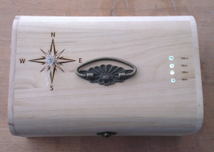
The box lid is equipped with a distance meter (here the four LEDS), a needle and has a compass rose engraved on it. Once the box closes, the needle spins on itself and finally stops to point at the direction of the goal. As you walk, the less blink or turn off to signal when you are getting closer.

Overall, it is a very versatile object that can be put to several uses. One of them would be to use it for a sort of “inverses geocaching”, only instead of having to find a certain object, you have to bring the object to the location. Once you reach the destination, you can let to world know of your success, and then re-program the GPS coordinates for the next person to take up the challenge.

Another idea would be to use the GPS Box for an original blind date. In this case, there are two possibilities: in a first instance, the content of the box would be a little surprise such as cinema tickets for two or the box could lead you to a romantic restaurant with table for two. However, if you use two boxes, it can become even more interesting. In this situation, there would be two boxes leading to the same location. One person would have one, and the other would have the second. By following the indications on the box, the two lonely souls would eventually be lead to the same location, where the box would open and again reveal a little surprise – perhaps a dinner for two.

The potential of the box does not stop here, however. Some of the others situations we found where the box can be used would be: a birthday present, a treasure hunt, a game for kids, team building, finding your way home… with a little bit of creativity, the possibilities are endless.

How does it work?

Apart from its secret and reward, the box contains quite a few other pieces of electronics and mechanic that make it work.

On the outside:

  • 4 LEDs + engraved distance meter
  • a direction needle
  • an engraved compass rose

On the inside:

  • a power supply (batteries)
  • two servo motors
  • two meshing gears with a 2:1 mechanical advantage
  • a simple lock mechanism
  • Arduino + WiFly shield

The Arduino contains the GPS data and, through the TinyGPS library, allows to calculate the distance and direction between the starting spot and the coordinates of the goal’s location. The LEDs turn on and off according to this information, displaying the distance (>= 1000m, 500m, 100m, and 50m) from the goal. This also operates one of the two Servo-Motors, turning the needle so that it points at the linear direction of the goal. Because of technical constraints, the indication of the direction is static – meaning that if you turn on yourself, the needle won’t correct its position. To overcome this issue, there is a compass-rose engraved on the lid, so that by orienting oneself to the north, one is able to stay on track.

When a defined minimal distance to the goal has been reached, the software switches to “Unlock-Mode”. At this point, the second servo motor is activated and switched its position from “Locked” to “Unlocked”, allowing to open the box. When this happens, all LEDs start blinking.

This signals to the user that he has reached his destination and can now open the box.

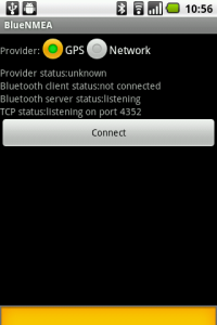
While the Arduino has a compatible GPS Hardware, it was not provided in the material we were supplied. We were thus forced to find an alternative solution (see Problems) to be able to receive and use the GPS data. The final prototype thus worked with the Wlan-Hotspot function of the Android phone, which used the BlueNMEA software to send GPS strings to the Arduino. These were then processed through the TinyGPS Library of the Arduino code.

As explained on the TinyGPS website:

“TinyGPS is designed to provide most of the NMEA GPS functionality I imagine an Arduino user would want ñ position, date, time, altitude, speed and course ñ without the large size that seems to accompany similar bodies of code.  To keep resource consumption low, the library avoids any floating point dependency and ignores all but a few key GPS fields.” – TinyGPS website

BlueNMEA is an Android application which sends location data over Bluetooth (RFCOMM) or TCP in the NMEA format.

Problems:

Due to time, budget and material constraint, we came across several issues while building our prototype:

  1.  The servo motors at our disposition would only turn 180°. The compass needle, however, needs to go all way round. The solution for this was a system of gears, one with a double amount of cogs or teeth than the other, thus creating a 2:1 mechanical advantage.  (amount of time involved: 2 hours + research on gear mechanisms)
  2. We did not have a GPS-shield compatible with the Arduino
  3. Transmission of GPS data via Bluetooth through a mobile phone also was not possible due to lack of a Bluetooth shield.

Solution: using phone as a WlanHotspot combined with the BlueNMEA app.  which sends GPS data over TCP. We could thus receive this data with the Arduino’s WiFI-Shield. (amount of time involved: 1 day until everything worked)

4. Energy supply: one 9V battery for the two servos + WiFly + Arduino + LED is not enough. Solution: more batteries

5. The engravings and the lock mechanism required very precise measurements, which were often tricky to get especially due to the rounded shape of the lid. Solution: patience, trial & error, lots and lots of measurements.

 Tips & Tricks:

Code snippet: getting Data from BlueNMEA

The following code snippet is used to get the GPS data through WiFly:

Conclusion and short video:

The SHW stage was a fun, engaging and challenging experience. Due to the limited time and materials we were often forced to think outside the box and find alternative solutions to get everything to work. However, once seeing everything fall into place and overcoming these problems was a very rewarding and useful learning experience.


(Thanks to Team WAMP for posting)
Energy Fight

Leave a comment

Energy Awareness

Nowadays fossile energy sources are exploited to the farthest extent and the need for alternative ways of energy production is urgent. The awareness of new and clean forms of energy is an important issue, that already the youngest members of our society should be given an understanding of. This is why we have developed a concept of achieving a higher energy awareness for children in a playful manner.


What is it?

Enery Fight is a game that increases energy awareness. It illustrates different possibilities to produce energy. The produced energy is used to manipulate the game board, which is a circle shaped acrylic glass panel, placed on top of the Engergy Fight box. To start the game you place a small ball in the centre of the board.

The two players battle each other by producing energy on the four sides of the box to get the ball into the hole on their side of the game board. The two ways to produce energy are wind, created by blowing into a wind wheel, and motion energy, by cranking a wooden wheel on the side of the box.

How does it work?

Inside the Energy Fight box there are 4 motors which are used as electricity generators. They are connected to the two wind wheels and the two wooden wheels. The energy production of the motors is each visualised by an LED placed on top of the box.

The game board is manipulated by two servo motors.  One servo motor tilts the game board to the left and right and the other one tilts it towards the players. The first servo motor is glued to the second motor and thereby affects the second motor’s tilt by its own motion. The second motor is glued to the game board. This construction allows to move the game board in all directions. All motors are connected to an Arduino Uno, which senses the voltage of the generators and translates it into the movement of the game board.


Values, Potentials and Next Steps

As children are the central target group of our game, it should be located in schools and playgrounds. Therefore, Energy Fight should be improved in several ways: First of all, it has to be waterproof to make the outdoor use possible, independent of the weather situation. Up to now, Energy Fight relies on external power supply. In order to bring the idea of energy awareness to its fullest, Energy Fight should be supplied just by solar power.
A further step could include that the players produce all the power needed to play the game by blowing the wind wheel and cranking the wooden wheels. It might also be interesting for the players to be informed of the actual amount of produced energy, thereby making the player aware of the relation of everyday energy consumption and the effort of producing energy.

Lessons Learned

It was very helpful to first make a plan and a low fidelity prototype. Therefore, gaffa tape was very useful! We first wrote the code for the Arduino and tested it with our low-fi prototype,  as can be seen in the video. Building on this already working version, we were able to add functionality and went over to the high fidelity prototype. A 3D model of the inside of the Energy Fight-box helped us to estimate the proportions of the inner parts of the game. This was a great outline when we designed the laser-cutter files.


We also designed a Fritzing sketch in a quite early state of our game. At that time, the LEDs were powered directly by the motors and not by the Arduino:

Because the cables overlapped each other, the Fritzing sketch did not help us so much so we did not integrate the latest changes. The power coming from the motors in the final game setting was not sufficient to enlighten the LEDs. That is why the LEDs had to be connected to the Arduino which translated the generated power to a larger, proportional amount of power for the LEDs.

An important step that had to be taken before finishing the project was testing our game in realistic settings. Thereby we found out that the energy-production and the movement of the game board had to be balanced in order to make the game enjoyable.

Presentation

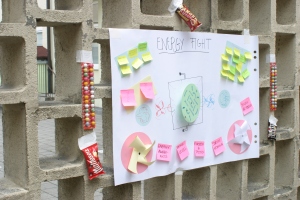
On the final day we presented our result: The Energy Fight Game. After an introduction to the game, Hendrik and Fabius battled against each other. The winner could choose between bubblegums, Maltesers, M&Ms and the First Prize: A “Ranger”. Afterwards, our game was free to be tested by the audience.


EnvironmentalJukebox

Leave a comment

Environmental awareness

As long as anyone can remember our environment has been providing food, water and a space to live for all of us. However our behavior changed and nowadays the environment also is a very important energy supplier. With our project, called the EnvironmentalJukebox, we wanted to make people aware that our environment has capabilities we haven’t ever thought of. It can be used to be creative. Especially aspects referring weather can be used to control a machine we have created. Since music plays a big role in many people’s lives we thought it could be very interesting to connect music and environmental aspects. This is how our project emerged.

What is it?

The EnvironmentalJukebox is, as its name implies, some kind of jukebox. However it’s not a common one. Instead of letting the user choose a certain type of music or radio station, the EnvironmentalJukebox creates and changes music by itself based on four environmental parameters: wind, light, rain and temperature. This music consists of piano-chords and a drum-beat. Once one or more of the environmental parameters change, music changes accordingly. For example, if the speed of the wind increases, the speed of the music increases. If it begins to rain, music gets louder. Temperature is used to decide whether chords within a minor or major key should be played and the amount of light is crucial for the pitch of the tones. The more light is captured the higher is the pitch of the tones and chords.

Video:

How does it work?

In the EnvironmentalJukebox two sensors (one for light, one for temperature) and two motors are used to measure the four parameters mentioned before. See below for a short tutorial how to measure wind-speed and waterflow.

To change the music once one or more of the environmental parameters change, the output of the sensors and motors need to be read. Therefore we use d an Arduino Uno, the Processing programming language and SoundCipher, a sound-library for Processing. See the next paragraph to learn how to connect Arduino to Processing.

At the beginning of our Processing application we had to create all chords we wanted to use. This can by done by float-arrays containing four values, e.g.:

float[] fisdur = {6.0, 10.0, 13.0, 18.0};

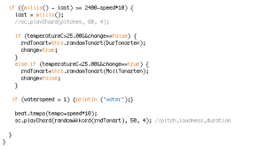
Each value represents one key on a regular piano. Furthermore we created keys each of which contains six chords and two ArrayLists, one for minor keys and one for major keys. As mentioned above, temperature is used to decide whether to play minor or major keys. To guarantee diversion to a certain degree, chords within a key are chosen randomly. So if the temperature doesn’t change for some time different chords can be heard. However all of them are within a certain minor or major key depending on temperature. To transponse chords when more or less light is available we wrote a method which ensures that chords are transponsed only within octaves to avoid disharmony.

Methods to chose keys/chords randomly and to transponse chords.

Lessons learned:

How to connect Arduino to Processing?

The first issue we had to encounter was how to connect the Arduino board to a higher programming language – in our case: Processing.  Certainly the Arduino library has to go into the processing-folder but there is still a library mismatch, if the library files “librxtxSerial.jnilib” and “RXTXcomm.jar” are not copied from your Arduino-program-folder to the Java library of your operating system. Now the “Firmata” library has to be loaded onto the Arduino board. This is done by launching Arduino and selecting “Examples” > “Firmata” > “StandardFirmata”. But now you have to be really careful! When you load a normal Arudino sketch the “Firmata” is being erased and you would have to load it once again on your Arduino! After this has been done properly a serial connection to the Arduino can be set up in Processing by using the statements

import processing.serial.*;
import cc.arduino.*;

and creating a serial Arduino object for example as

Arduino arduino = new Arduino(this, Arduino.list()[4], 57600);

This object now can be addressed with most Arduino commands but unfortunately not with all, what brings us to our next issue.

Circuit Diagram (made with Fritzing)

How to measure wind?

Since we had to measure the speed of wind for our project the first idea was to simply grab the fan-speed of an old PC-fan that has not been connected to current but instead is just grounded with its sensor pin connected to one of the digital Arduino-pins. This works fine since there are many examples of Arduino-code for grabbing fan speed but sadly none of them worked for us in Processing, since not all needed Arduino commands are supported. So our solution was to mount the rotor of one fan to an electric motor and measure the speed by tracing the outgoing current. This can be done by connecting the plus-port of the motor to an Arduino’s analog input port. The value being read from the port (range goes from 0 to 1023) reflects the outgoing current of the motor.

Measuring the speed of wind was not so easy as it my sound at first.

How to measure water flow?

To measure the amount of rain the workflow is basically the same. Once the rotor was attached to the motor we had to use a pipe and a some kind of container to gather water on the top of the jukebox. For a working construction it’s crucial that the diameter of the pipe matches the width of the rotor. Furthermore the water has flow with a certain speed and the pipe needs to be perfectly aligned to the rotor to make it turn around. Unfortunately we didn’t test it thoroughly enough so this measurement didn’t work as we had expected.

Measurement of water flow can also be done by a rotor attached to a motor.

Parallel programming with processing?

Programming Processing is very similar to coding Arduino directly using the Arduino programming tool. There is a setup() method and also a permanently called method that is named draw() and not loop() like in Arduino. This is all in all no problem but when it comes to doing things real-time parallel it can get a little bit tricky. In our case we needed to play chords and a beat at the same time. But since only one of this can be done at one moment in the draw() method we had to find  a workaround. Our solution was to create different objects of our sound-library (SoundCipher) a SoundCipher-object and an SCScore-object and call them consecutive so (with a little tweaking) the sound seemed to be absolutely parallel. An other method could have been a callback-method that allows the program to jump back into the setup()-method, but this was a little to time intense for our purpose.
To give the impression of parallel execution the beats have to be played immediately before the chords.

Values and Potentials:

The Environmental Jukebox is a tool that creates random-music that always sounds very harmonic and adepts to the environmental influences. So it can be used as a tool of inspiration for musicians when they place it on some outdoor locations where they like to compose their tunes. Due to the fact that the Jukebox always sticks to a certain key and only changes it when the temperature drops below 20° it also works really nice as an accompanying instrument that can be joined by any thinkable solo instrument. Also the acoustic representation of the environment itself could make the Jukebox interesting for any environmentally aware companies or organizations that would like to have some smooth background-tunes at their place that are created by nature itself.

Next Steps:

Thus music almost offers endless possibilities, the options how to improve and enhance the Environmental Jukebox seem to be without much limit, too. Adding multiple channels and instruments, more sensors or even building a portable device, that not only reacts on environmental influences but also on the ones of his wearer, are just a few of the possibilities that could be done in the future. For more human interaction an interface with real instruments would certainly push the jukebox more in an interactive direction, that would give it more of the attitude of a real instrument, that could join in any musical arrangement. Even the combination of many devices to whole automated concerts that depend on environmental energies would be thinkable and would certainly be a lot of fun!

TeamTwist

Leave a comment

We all know how to open a box, but what if the box doesn’t want to be opened?

You are geocaching and found the cache. It’s slightly open but every time you get close, the mysterious chest locks itself. As you look around you see some strange objects blinking. Soon you notice that each object is reacting with your moves but there are far too many objects to activate all of them at the same time on your own. So if you don’t have a partner with you, go home or look for one, because you are playing TeamTwist.

What is it?

When playing TeamTwist you have to interact with the strange objects, called widgets. To finally open the chest, you have to activate different widgets depending on the current level. After each level the chest opens itself a little bit further.

After twisting yourself more and more from level to level, the chest is finally willing to let you raise its treasure.

How does it work?

The game consists of the chest and several widgets.

The chest

In an old sparkling wine box in we placed two servos: One for lifting the lid and the other to lock the box. Our first prototype (as you see in the video) was just a shoe box. Furthermore the box is secured by a light barrier (ultrasonic sensor) which prevents people to approach it before the end of the game.

The widgets

Although there are lots of possibilities to construct the widgets, we decided to build four different kinds of widgets for a start.

Each widget is featured with LEDs that blink when trying to attract the players attention. But they shine continuously when the player handles the widget the right way.

Human Conducting widget
Form a chain, linking both parts of the widget.
This widget consists of two nearly identical parts. Each part has a large contactor area composed of multiple stripes of copper tape (Yes, we use the players as conducting medium, but we hope that our test persons are still alive and well). One contactor is supplied with 5V whereas the other one has just a “sensor line-out” to measure the incoming current, telling us whether the players are electrified (a connection between both parts).

Light Widget
Shade or illuminate it e.g. by directing the cup to a light source.
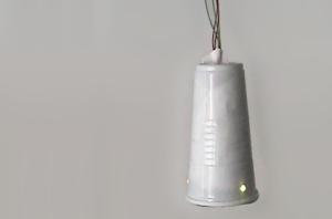
We used plastic cups in which we placed a LDR and a layer of kitchen foil to scatter the incident light.

Weight Widget
Put a heavy object on it e.g. your partner.
Our first prototype consisted of the following layers (bottom to top): floor pads, acryl glass, FSR (Force Sensing Resistor), a layer of rubber to enlarge the working surface of the sensor and again acrylic glass. Since this was too slippery for Sebastian’s shoes we applied large snippets of the evil-smelling rubber blanket we found in the workshop. And it worked pretty well!

Distance Widget
Get close or keep away.
We fitted an infra-red distance sensor into an acryl glass triangle.

The coding

The game cycle is shown in the diagram below.

Further Ideas

TeamTwist can be easily extended by adding new or other widgets. Further widgets could be:

  • a spirit level widget, which must be held in a certain direction
  • an object, that has to be squashed or stretched

Lessons learned

Construct something that fits into a single movable box which doesn’t depend on the location for the final presentation: It took us the whole last day to extend the wires of the widgets to prepare the TeamTwist arena – lost crucial time for polishing and preventing heavy malfunctions.

Day 7 – The finish line

Leave a comment

Unfortunately this was the last day of the Sketching with Hardware course. In the morning all teams worked hard to finish their prototypes and to make the last changes. At lunchtime the inner yard and the garage were prepared for the final presentation by setting up tables and power strips. At about 13:30 students, research assistants and visitors being interested in the course came together to participate in the final presentation. One after another team introduced their prototype and talked about the idea the project is based on. Everybody was asked to try it out and to ask questions. After the presentation everything was cleaned up. Our advisors and we met again to consider the results of the course and to discuss feedback. This was the end of the Sketching with Hardware course.

Thanks again to our advisors, Hendrik and Sebastian and to all teams for this interesting and inspiring course. I think we all had a lot of fun and learned many new things.

Day 5: Building, building, testing

Leave a comment

After the first tests yesterday, today everyone was busy building their prototypes. So most of us spend at least half of our time in the workshop: testing material, cutting, screwing, gluing, and getting the electronics to work.

At the end of the day, every project looked a bit more developped and presentable. Here are some impressions of today:

Though no one was stressed today, I guess tomorrow will be different.

Day 4: The building phase begins

Leave a comment

The fourth day mainly consisted of building prototypes for the projects. There was no schedule for the day, so each group was free to manage the time on their own.

After the project ideas were set on Monday, for most of the groups the main target for the day was to verify the technical feasability of their ideas. For each project, that meant a different challenge. Mostly, that was to get a working circuit with the intended functionality on the breadboard.

Due to the diverse nature of the projects, a lot of different technologies were explored. From Wi-Fi to Xbee wireless transmitters, GPS, Motors and a lot of different sensors, each group had its own hardware set to tinker with. Even the smell of the laser-cutting machine was noticeable a few times the day.

While building the prototypes, it got obvious that some ideas didn’t work out as expected. Hence, two groups changed their project topics for the sake of better feasability. After all, it seemed to be a successful and funny day for everyone, thanks to Hendrik’s extensive support.

For most of the groups the lab day ended at 5, while some eager groups tortured their Arduinos till 8 in the evening.

Day 3: Concepts

Leave a comment

This was the last vacation day for laser cutter, soldering iron, drilling machine and all other tools that will have to work tremendously hard till the end of the week.

The day began with the presentation of each groups first vague ideas followed by a short discussion which idea should be realized and how it could be improved. We heard about vuvuzela traffic lights, unhittable footballs and computer mice, that force the user to ride the bike.

Armed with post-its and whiteboard markers each team spent the next hours with brainstorming and elaborating their most promising idea.

At the second presentation in the afternoon most vague ideas had become concrete concepts.

So, let’s make some noise!